
Swivel joint with stepped bearing races

a stepped bearing and swivel joint technology, applied in the direction of hose connection, rod connection, mechanical apparatus, etc., can solve the problems of reducing the integrity of the swivel joint, brinelling reducing the life of the bearing race, so as to reduce the weight and cost, improve sealing, and eliminate the brinelling of the bearing race

Inactive Publication Date: 2007-06-19
FMC TECH INC
View PDF35 Cites 25 Cited by
  • Summary
  • Abstract
  • Description
  • Claims
  • Application Information

AI Technical Summary

Benefits of technology

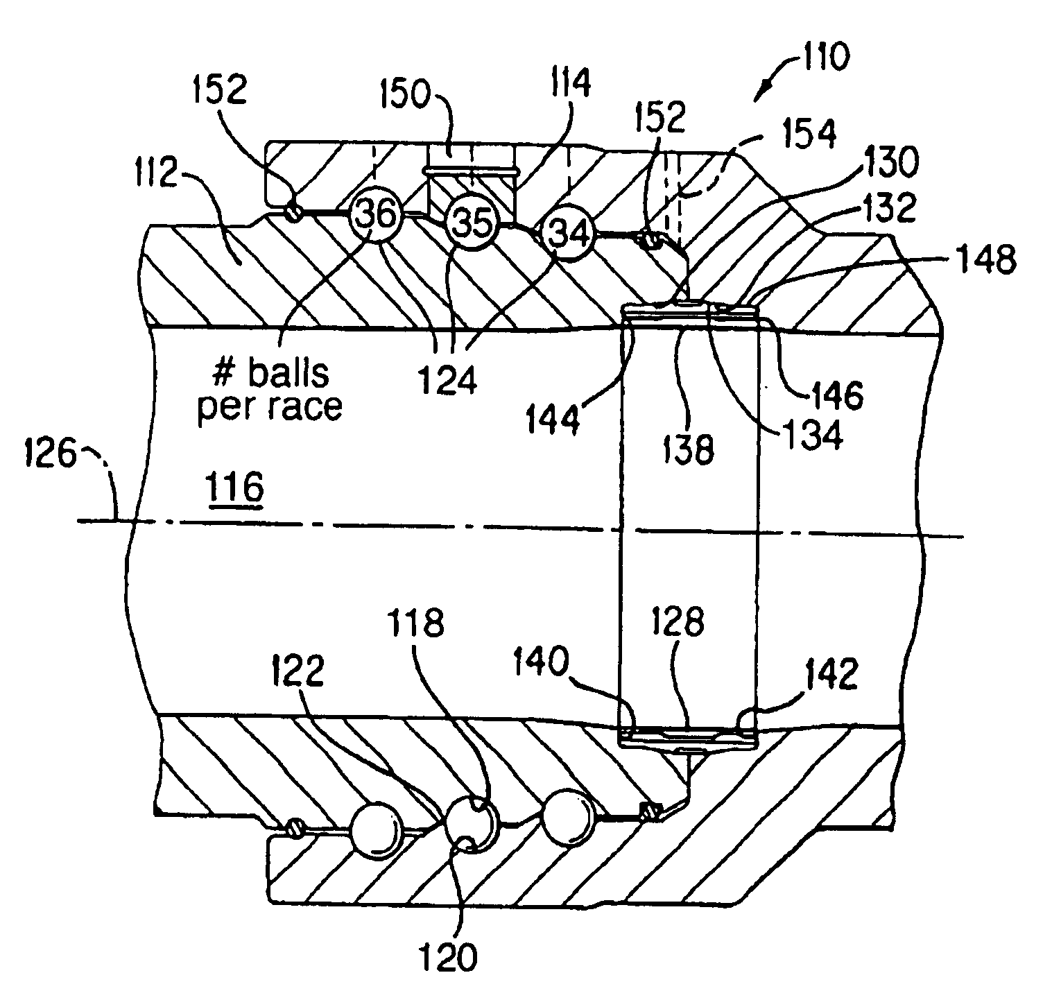
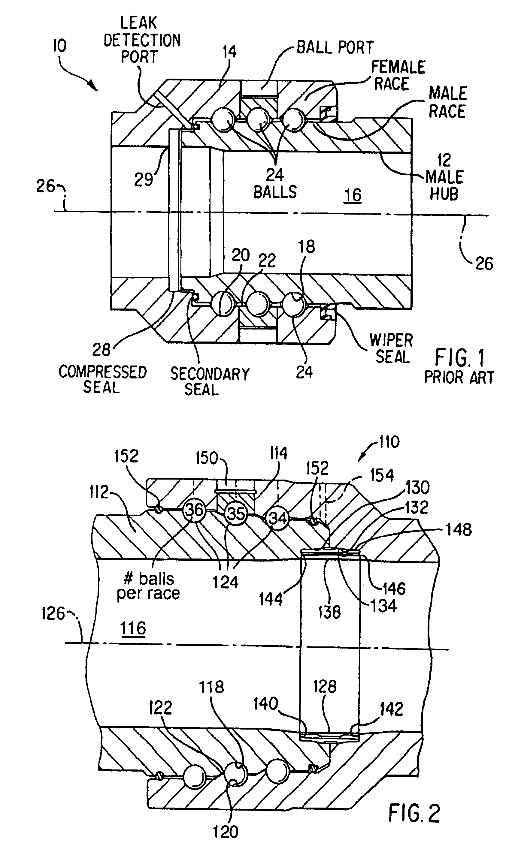
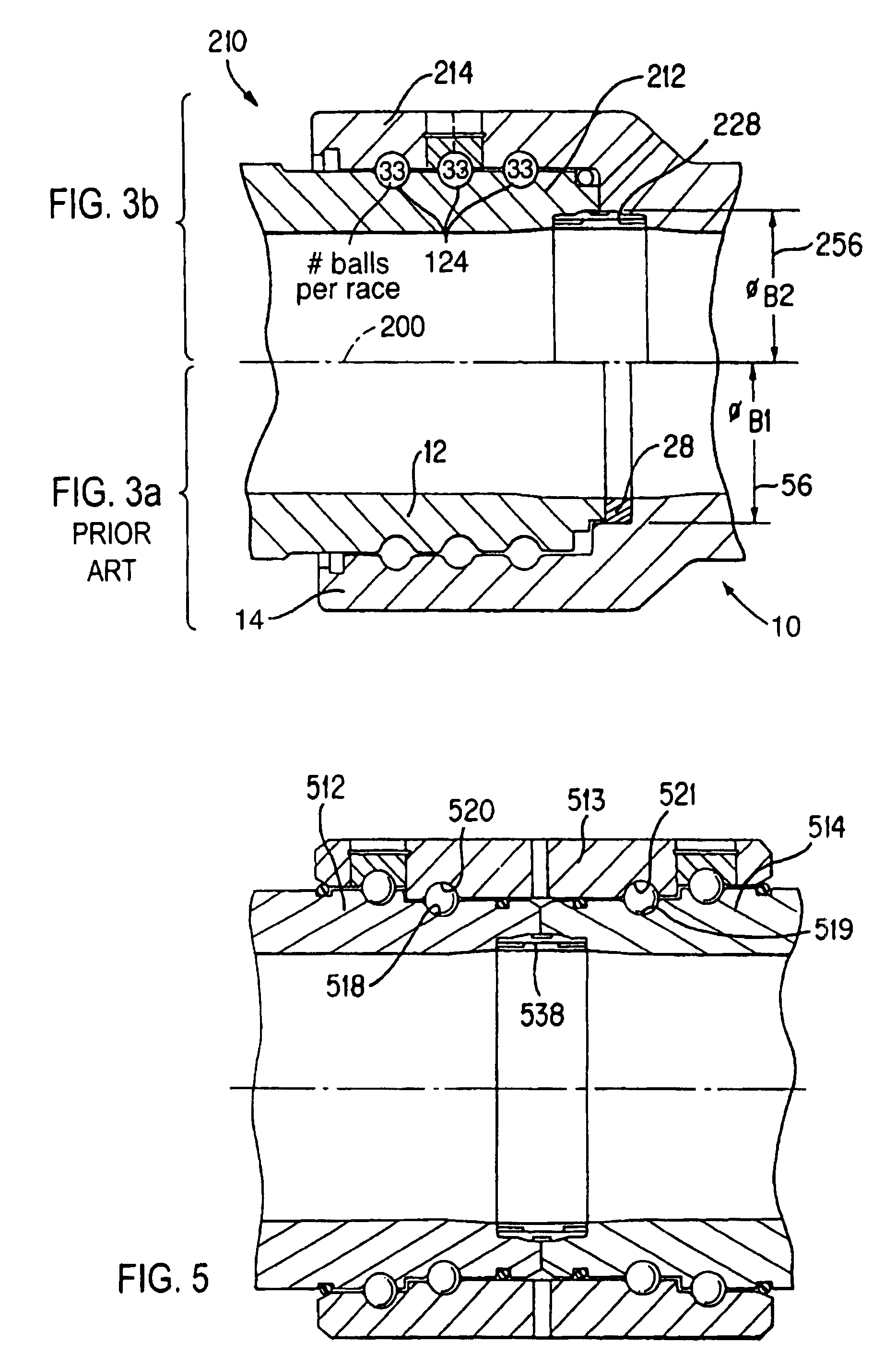
[0005]The present invention improves sealing under extreme conditions and specifically eliminates bearing race brinelling at pressures much greater than is attained with conventional or known swivel joints with minimal increase in weight and cost. This stepped configuration more equally distributes hydrostatic end loading to each bearing race section, enabling maximum total end loading while minimizing load concentration on a particular bearing race. In addition, the stepped configuration permits the male member to have a relatively larger cross section under the bearing race without increasing the overall diameter of the swivel joint, which enables the male member to withstand a relatively greater amount erosive wear and thereby improves the overall integrity of the swivel joint.

Problems solved by technology

Even with multiple bearing races high pressures can sometimes cause deformation or brinelling of the bearing races.
Such brinelling relaxes the compression of the seal between the male and female members and causes the seal to leak, preventing the swivel joint from swiveling smoothly under pressure and reducing the bearing race life significantly.
In addition, errosive wear in the male member under the bearing race can quickly reduce the integrity of the swivel joint.

Method used


Image

  • Swivel joint with stepped bearing races
  • Swivel joint with stepped bearing races
  • Swivel joint with stepped bearing races

Examples


Embodiment Construction

[0014]FIG. 1 shows a known, prior art swivel joint 10 having a male connector 12 rotatably received inside of a female connector 14. A sealed fluid flow passage 16 is formed therethrough, in communication with fluid conduits or pipes (not shown) extending from each connector. Each connector 12, 14 has respectively formed thereon a plurality of annular grooves 18, 20. When the connectors 12 and 14 are inserted together, the grooves 18 and 20 align with each other forming annular bearing races 22. A plurality of ball bearings 24 are housed in each race 22 to provide bearing support and to enable swiveling of the connectors 12, 14 relative to each other. The races 22 and ball bearings 24 are coaxially positioned around a center axis 26 of the flow passage 16. The races 22 all have substantially the same radius. An annular elastomer compression seal 28 is positioned between axial faces of the male connector 12 and the female connector 14 to prevent fluid flow therebetween. The compressi...


PUM


Abstract

A swivel joint comprises a tubular male member having at least first and second outer annular grooves formed on an outer surface, a tubular female member having at least first and second inner annular grooves formed on an inner recess, and a plurality of balls disposed in at least first and second annular races which are formed by the alignment of the first and second outer grooves with the first and second inner grooves when a first end of the male member is received within the recess of the female member. In addition, the radius of the first race is greater than the radius of an adjacent race closer to the first end of the male member, and the number of balls in the first race is just one more than the number of balls in the adjacent race closer to the first end.

Description

[0001]This application is a continuation of U.S. patent application Ser. No. 08 / 742,520 filed on Nov. 1, 1996, <?insert-start id="INS-S-00002" date="20070619" ?>now U.S. Pat. No. 6,164,707<?insert-end id="INS-S-00002" ?>, which is a continuation of U.S. patent application Ser. No. 08 / 260,160 filed on Jun. 15, 1994, now abandoned, both of which applications are hereby incorporated herein by reference.BACKGROUND OF THE INVENTION[0002]The present invention relates to a swivel joint and, more particularly, to a swivel joint having stepped bearing races.[0003]Swivel joints are used in connect fluid pipes in oilfields and in other applications. Swivel joints are generally comprised of interfitting male and female members rotatably connected by a bearing assembly. Typically, inner and outer grooves are incorporated in the male and female members to form a bearing race, and a plurality of ball bearings are housed within the race. Higher demand for compatibility with increased s...

Claims


Application Information

Patent Timeline
Patent Type & Authority Patents(United States)
IPC IPC(8): F16L27/04F16L27/00F16B7/20F16C19/02F16L27/08
CPCF16L27/0824F16L27/0828F16C2361/00
Inventor UNGCHUSRI, TEPCASTILLO, SERGIO A.
Owner FMC TECH INC
Learn More