Seat belt tension prediction

a seat belt and tension prediction technology, applied in the direction of instruments, pedestrian/occupant safety arrangements, force/torque/work measurement apparatus, etc., can solve the problem of complete loss of contact with the seat belt, and achieve the effect of accurate calculation of seat belt tension

Inactive Publication Date: 2010-10-05
JOYSON SAFETY SYST ACQUISITION LLC
View PDF30 Cites 19 Cited by
  • Summary
  • Abstract
  • Description
  • Claims
  • Application Information

AI Technical Summary

Benefits of technology

[0017]The instant invention overcomes the aforementioned problems by providing a seat belt tension prediction system employing an accelerometer and a seat weight sensor to accurately determine the tension in a vehicle seat belt and thereby discriminate between the presence of a tightly belted child seat or other object and an adult occupant.
[0031]Furthermore, by sensing the amount of tension present in the seat belt, the deployment of an airbag may be inhibited in the presence of infant seats or in situations where occupants are small so as to reduce their risk of injury from the inflating air bag. Therefore, a system that can reliably predict the amount of tension present in a seat belt may be used to great advantage in vehicle safety systems.
[0032]One significant advantage of the instant invention is that it does not require numerous ancillary components that are in direct contact with the seat belt system. The present invention can predict whether there is significant tension in the seat belt without directly measuring seat belt tension.
[0033]Therefore, one object of the instant invention is to provide a seat belt tension measurement system that does not require a mechanism in direct contact with the seat belt or its associated assembly.
[0035]A yet further object of the present invention is to provide a seat belt tension prediction system that requires minimal additional components beyond a seat weight measurement means and the attendant processor adapted to receive and process various vehicle instrumentation signals. The instant invention requires only an accelerometer or equivalent acceleration sensing device and a conventional microprocessor or equivalent processing means in conjunction with a seat weight sensor to accurately calculate seat belt tension.

Problems solved by technology

A “free” or unbelted mass positioned on a vehicle seat will bounce up and down on the seat and may, for example, completely lose contact with the seat in extreme cases.

Method used


Image

  • Seat belt tension prediction
  • Seat belt tension prediction
  • Seat belt tension prediction

Examples


Embodiment Construction

)

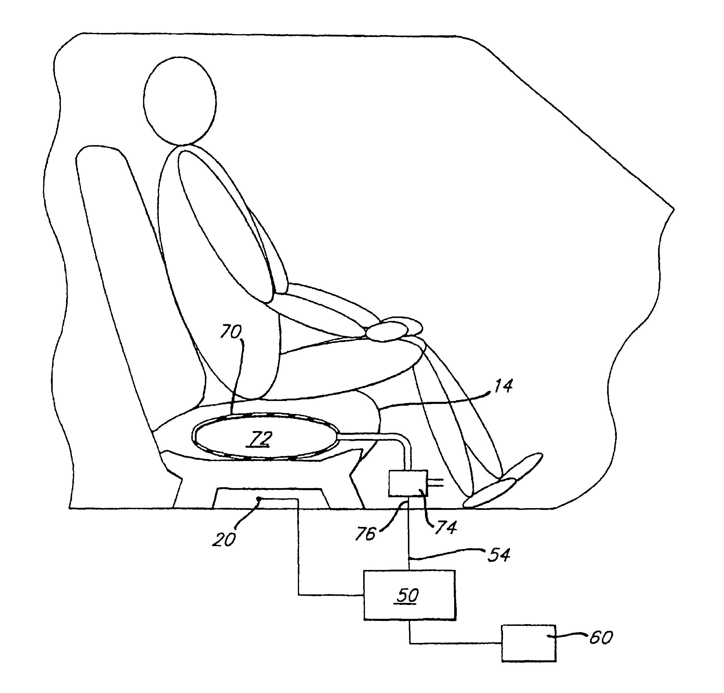
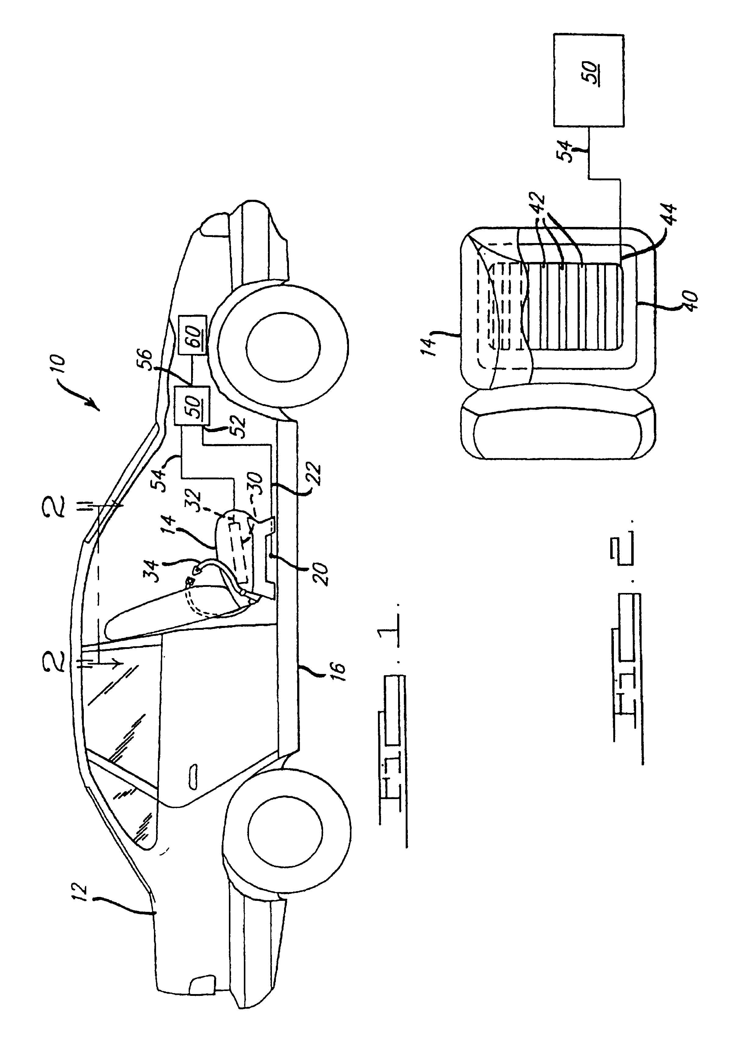
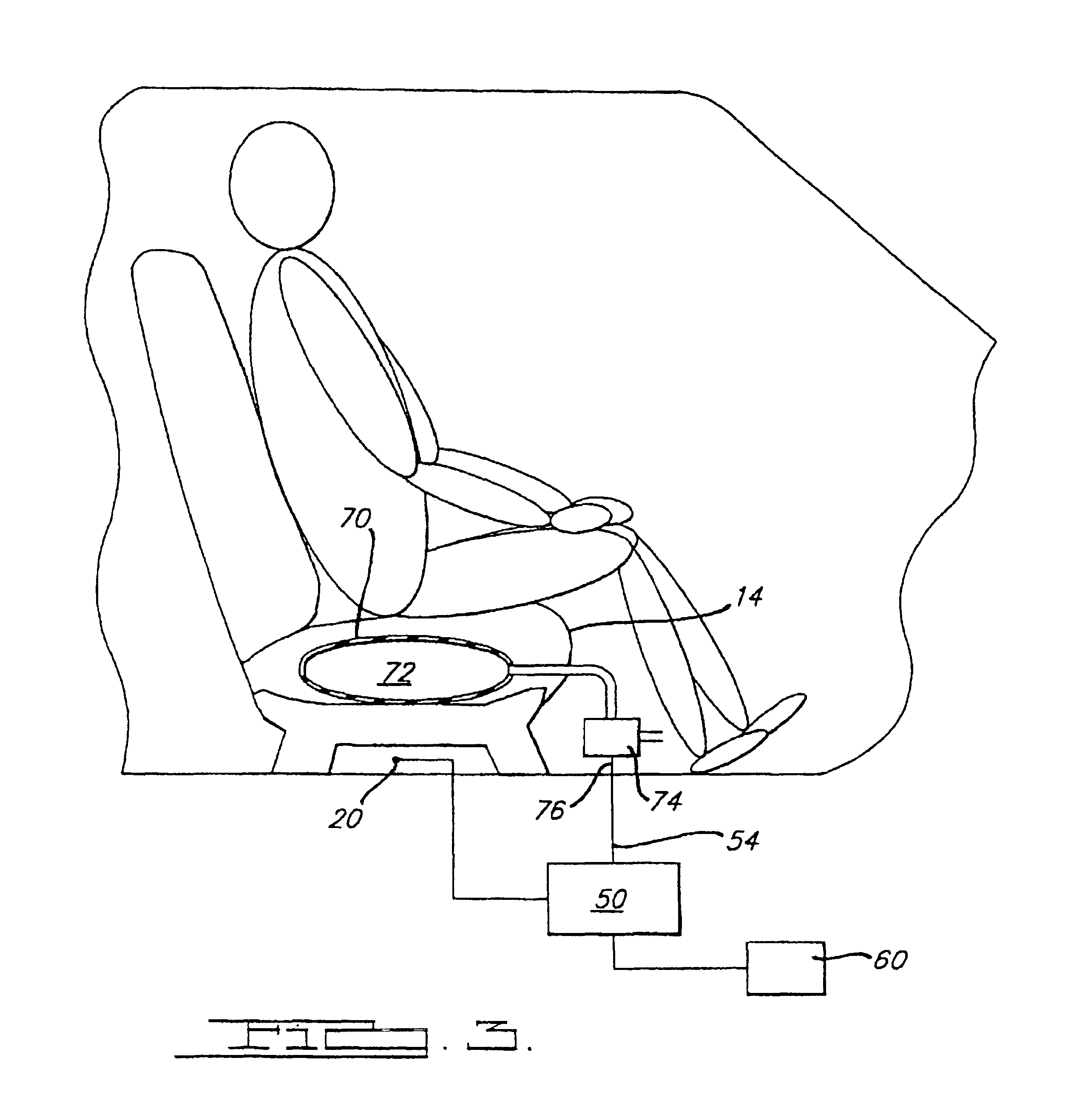
[0043]Referring to FIG. 1, a seat belt tension prediction system and method 10 for a vehicle 12 having a seat 14 is comprised of an accelerometer 20 and a seat weight sensor 30. The accelerometer 20 is provided with an output signal 22 that is responsive to the amount of vertical acceleration acting upon the vehicle 12 and, therefore, on the vehicle seat 14. The accelerometer 20 must be rigidly secured to a vehicle structural member 16 that experiences the same vertical acceleration that the vehicle seat 14 is subjected to when traversing variations in terrain. In a preferred embodiment of the instant invention the resolution of the accelerometer 20 is greater than 0.005 g to provide sufficient sensitivity to small variations in vertical acceleration.

[0044]The seat weight sensor 30 is provided with an output signal 32 that is responsive to the amount of force exerted downwardly on the vehicle seat 14. Accordingly, the seat weight sensor output signal 32 will also be responsive to a...


PUM

PropertyMeasurementUnit
timeaaaaaaaaaa
tensionaaaaaaaaaa
vertical accelerationaaaaaaaaaa

Abstract

A vehicle seat belt tension prediction system and method comprises an accelerometer having an output signal responsive to vertical acceleration of the vehicle, a seat weight sensor having an output signal responsive to the force exerted by a mass resting on the seat, and a processor means for calculating seat belt tension. The processor is provided with a plurality of inputs operatively coupled to the accelerometer output and seat weight sensor output. Suitable programming is provided to instruct the processor to calculate the average mass resting on the vehicle seat and predict the force that should be exerted on the seat for a measured level of vertical acceleration assuming zero belt tension. The processor then compares the actual force measured by the seat weight sensor with the predicted force to determine seat belt tension thereby obviating the necessity of complex hardware in physical contact with the seat belt system.

Description

CROSS REFERENCE TO RELATED APPLICATIONS[0001]More than one reissue application has been filed for reissue of U.S. Pat. No. 6,161,439. In particular, two applications for reissue of U.S. Pat. No. 6,161,439 have been filed: Reissue application Ser. No. 10 / 326,170, filed Dec. 19, 2002, and the present reissue application, which is a divisional reissue application thereof.[0002]The instant application claims the benefit of U.S. Provisional Application Ser. No. 60 / 046,233, filed May 12, 1997.[0003]Co-pending U.S. application Ser. No. 08 / 993,701 entitled “Seat Weight Sensor Having Fluid Filled Bladder”, filed on Dec. 18, 1997, claiming benefit of U.S. Provisional Application Ser. No. 60 / 032,380 filed on Dec. 19, 1996, and assigned to the assignee of the instant invention discloses a hydrostatic weight sensor comprising a fluid filled bladder and a pressure sensor for sensing the weight of an occupant in a vehicle seat for controlling a safety restraint system. U.S. application Ser. No. 08...

Claims


Application Information

Patent Timeline
Patent Type & Authority Patents(United States)
IPC IPC(8): G01L1/26B60N2/90B60R21/01B60R21/015B60R21/16B60R22/10G01G19/414
CPCB60N2/002B60R21/01556G01G19/4142B60R21/01516B60R2021/01317B60R2021/01325
Inventor STANLEY, JAMES G.
Owner JOYSON SAFETY SYST ACQUISITION LLC
Why Eureka
Try Eureka