Method and apparatus for providing selectable output voltages
a technology of output voltage and selectable voltage, which is applied in the direction of variable transformer, variable inductance, inductance, etc., can solve the problems of longer delivery time and more expensiv
- Summary
- Abstract
- Description
- Claims
- Application Information
AI Technical Summary
Benefits of technology
Problems solved by technology
Method used
Image
Examples
first embodiment
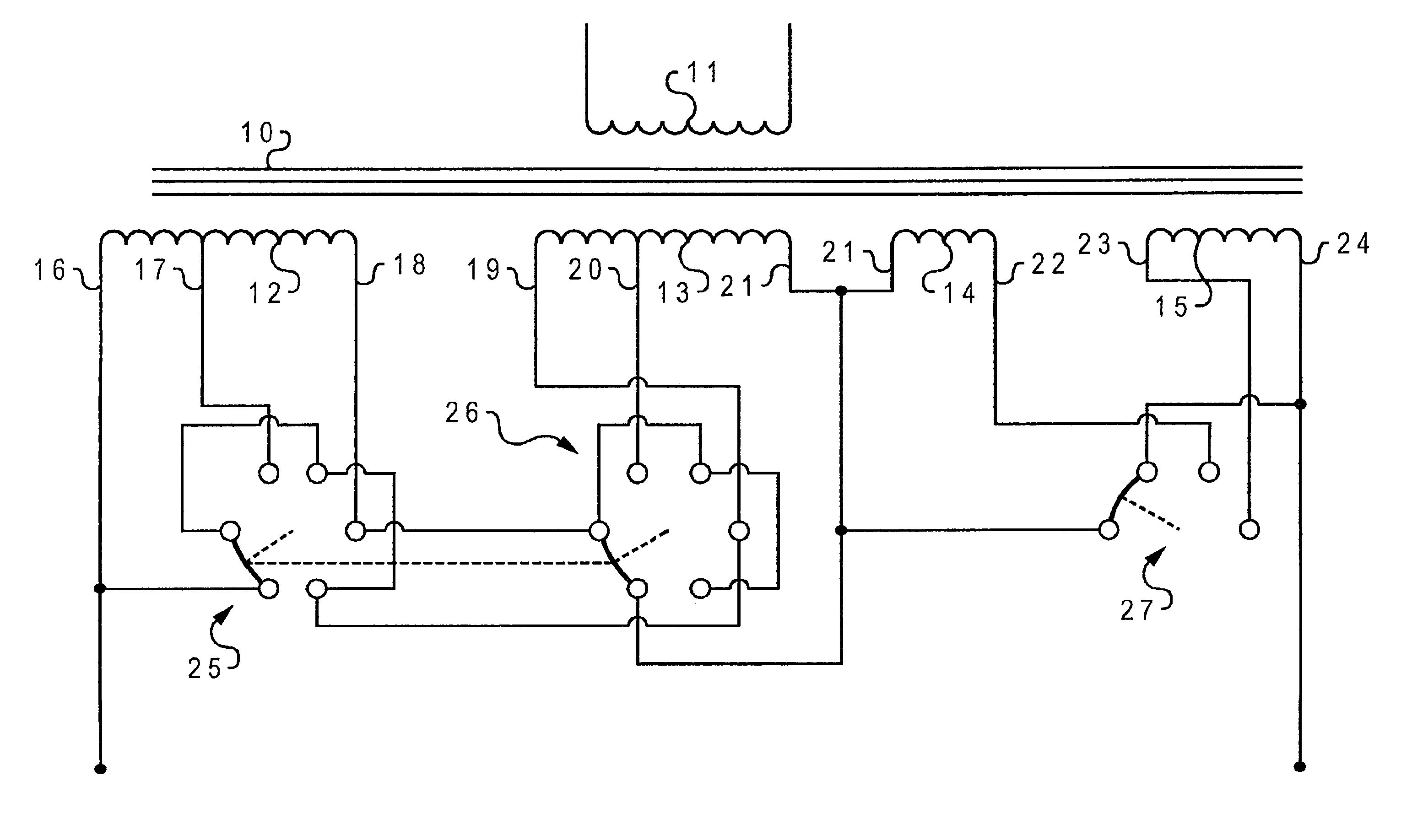
[0031]In the present invention, shown in FIG. 4 of the drawings, the schematically illustrated transformer 10 has a primary winding 11, two isolated center tapped secondary windings 12 and 13 and two additional isolated secondary windings 14 and 15. Electrical access leads 16 through 24 provide electrical contact to the winding ends and taps as shown. The turns ratios of the secondary windings are 6:6:1:1 for windings 12, 13, 14, and 15, respectively.
[0032]Leads 16 through 21 are interconnected through a pair of ganged five-position bridging tap changers 25 and 26 and wired as a three-position series-parallel-series switch. Leads 21 through 24 are interconnected through a three-position bridging tap changer 27. Both three-position and five-position bridging tap changers are relatively inexpensive, off-the-shelf switches.
[0033]According to the invention, the system of FIG. 4 provides a selection of any of nine distinct voltage outputs at transformer secondary output terminals 28 and ...
sixth embodiment
[0040]In the present invention shown in FIG. 9, the secondary windings 52″ and 53″ are, as in the previous two embodiments, tapped at thirds as are secondary windings 54″ and 55″. The turns ratio relationship between the four secondary windings of the system of FIG. 8 is such that windings 54″ and 55″ each comprise a three unit turns group and windings 52″ and 53″ each comprise a twenty-one unit turns group.
[0041]With the leads of windings 52″ and 53″ connected by series-parallel-series switch, ganged switches 68″ and 69″, as in the previous embodiments, and the leads of windings 54″ and 55″ are interconnected through a seven-position bridging switch 70″, as shown, the system of FIG. 9 provides twenty-eight different voltage outputs available in one voltage unit steps from twenty-one to forty-eight voltage units. The highest to lowest winding loss ratio of the system of FIG. 9 is 1.286. The highest to lowest loss ratios of FIG. 1 and FIG. 2 adapted to this voltage range are 1.495 an...
PUM
| Property | Measurement | Unit |
|---|---|---|
| voltages | aaaaa | aaaaa |
| output voltages | aaaaa | aaaaa |
| electrical power | aaaaa | aaaaa |
Abstract
Description
Claims
Application Information
 - R&D
- Intellectual Property
- Life Sciences
- Materials
- Tech Scout
- Unparalleled Data Quality
- Higher Quality Content
- 60% Fewer Hallucinations
Browse by: Latest US Patents, China's latest patents, Technical Efficacy Thesaurus, Application Domain, Technology Topic, Popular Technical Reports.
© 2025 PatSnap. All rights reserved.Legal|Privacy policy|Modern Slavery Act Transparency Statement|Sitemap|About US| Contact US: help@patsnap.com


