Adjustable mounting bracket for flat panel display

a technology of mounting brackets and flat panels, applied in the field of adjustable mounting brackets, can solve the problems of affecting the practical application affecting the appearance of flat panel displays, and presenting certain problems in the process of mounting them to a vertical surface, so as to prevent the disengagement

Active Publication Date: 2012-10-02
LEGRAND AV INC
View PDF27 Cites 7 Cited by
  • Summary
  • Abstract
  • Description
  • Claims
  • Application Information

AI Technical Summary

Benefits of technology

[0008]In a specific embodiment of the mounting bracket, the first traversing mount and the second traversing mount are flexibly coupled between the wall bracket and the display bracket, thereby enabling misalignment of the positions of the first traversing mount and the second traversing mounts to adjust the skew of the display bracket relative to the wall bracket. In another specific embodiment, the first traversing mount and the second traversing mount are flexibly coupled to enable rotation within a plane that is parallel to the wall on which the wall bracket is disposed. In another specific embodiment of the mounting bracket, the first traversing mount is flexibly connected to the first actuator and the second traversing mount is flexibly connected to the second actuator, thereby enabling misalignment of the positions of the first traversing mount and the second traversing mount to adjust the skew of the display bracket relative to the wall bracket.
[0009]In a specific embodiment of the mounting bracket, the first actuator and the second actuator are threaded rods that engage the first traversing mount and the second traversing mount, respectively. The threaded rods extend to a peripheral location on the mounting bracket, thereby enabling access for actuation thereof by a user. In another specific embodiment, the display bracket is configured as a first portion and a second portion that are independently supported, thereby enabling adjustment of their spacing adaptation to the mounting configuration of the flat panel display.
[0010]In a specific embodiment of the mounting bracket, the first traversing mount and the second traversing mount are removably disposed between the wall bracket and the display bracket. In a refinement, the mounting bracket also includes a horizontal mounting flange disposed to removably engage the first traversing mount and the second traversing mount, thereby enabling adjustment of the horizontal position of the display bracket relative to the wall bracket. In another refinement, the mounting bracket further includes a mount lock coupled to selectively lock the position of the display bracket to the wall bracket, and, the mount lock is selectively actuated by a lock actuator. In a further refinement, the mount lock is positioned to urge the first traversing mount and the second traversing mount against the horizontal mounting flange, thereby preventing disengagement there from. The lock actuator may be a threaded rod that engages the mount lock and extends to a peripheral location on the mounting bracket. The lock actuator may engage the first actuator or the second actuator.
[0011]The present invention also teaches a mounting bracket apparatus for adjustably supporting a flat panel display from a wall configured as follows. A wall bracket has a first horizontal flange aligned in parallel with a second horizontal flange. A first display bracket has a first traversing mount driven along a first linear axis and engaged with a first threaded rod actuator that extends to a peripheral location on the mounting bracket. The first traversing mount has a curved extension formed to supportively engage the first horizontal flange and enable rotation of the first display bracket along a plane parallel to the wall on which the wall bracket is mounted. The first display bracket further includes a first mount lock slidably positioned along the first threaded rod actuator and aligned to be urged against the second horizontal flange by a first lock actuator that is concentric to and engaged with the first threaded rod, and that extends to a peripheral location on the mounting bracket. The mounting bracket also includes a second display bracket that has a second traversing mount driven along a second linear axis and engaged with a second threaded rod actuator that extends to a peripheral location on the mounting bracket. The second traversing mount has a curved extension formed to supportively engage the first horizontal flange and enable rotation of the second display bracket along the plane parallel to the wall on which the wall bracket is mounted. The second display bracket further includes a second mount lock slidably positioned along the second threaded rod actuator that is aligned to be urged against the second horizontal flange by a second lock actuator that is concentric to and engaged with the second threaded rod, and that extends to a peripheral location on the mounting bracket. The first display bracket and the second display bracket are independently positionable along the first horizontal flange, thereby enabling adjustment of the horizontal position of the flat panel display, and further enabling adjustment of the spacing between the first display bracket and the second display bracket to allow adaptation to the mounting configuration of the flat panel display.

Problems solved by technology

Flat panel displays are large, heavy, and expensive, and therefore the process of mounting them to a vertical surface is daunting.
Installers and users who do their own installation typically avoid repetitive mounting and dismounting of a flat panel display because of the difficulty of the task and the risk of damage involved.
While this arrangement is straightforward, it does present certain problems in practical applications.
In addition, structural mounting fasteners, such as lag bolts, toggle bots, and expansion fasteners are not precise instruments by their very nature.

Method used


Image

  • Adjustable mounting bracket for flat panel display
  • Adjustable mounting bracket for flat panel display
  • Adjustable mounting bracket for flat panel display

Examples


Embodiment Construction

[0045]Illustrative embodiments and exemplary applications will now be described with reference to the accompanying drawings to disclose the advantageous teachings of the present invention.

[0046]While the present invention is described herein with reference to illustrative embodiments for particular applications, it should be understood that the invention is not limited thereto. Those having ordinary skill in the art and access to the teachings provided herein will recognize additional modifications, applications, and embodiments within the scope thereof and additional fields in which the present invention would be of significant utility.

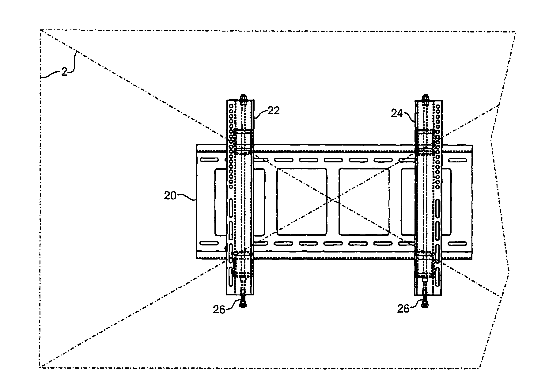
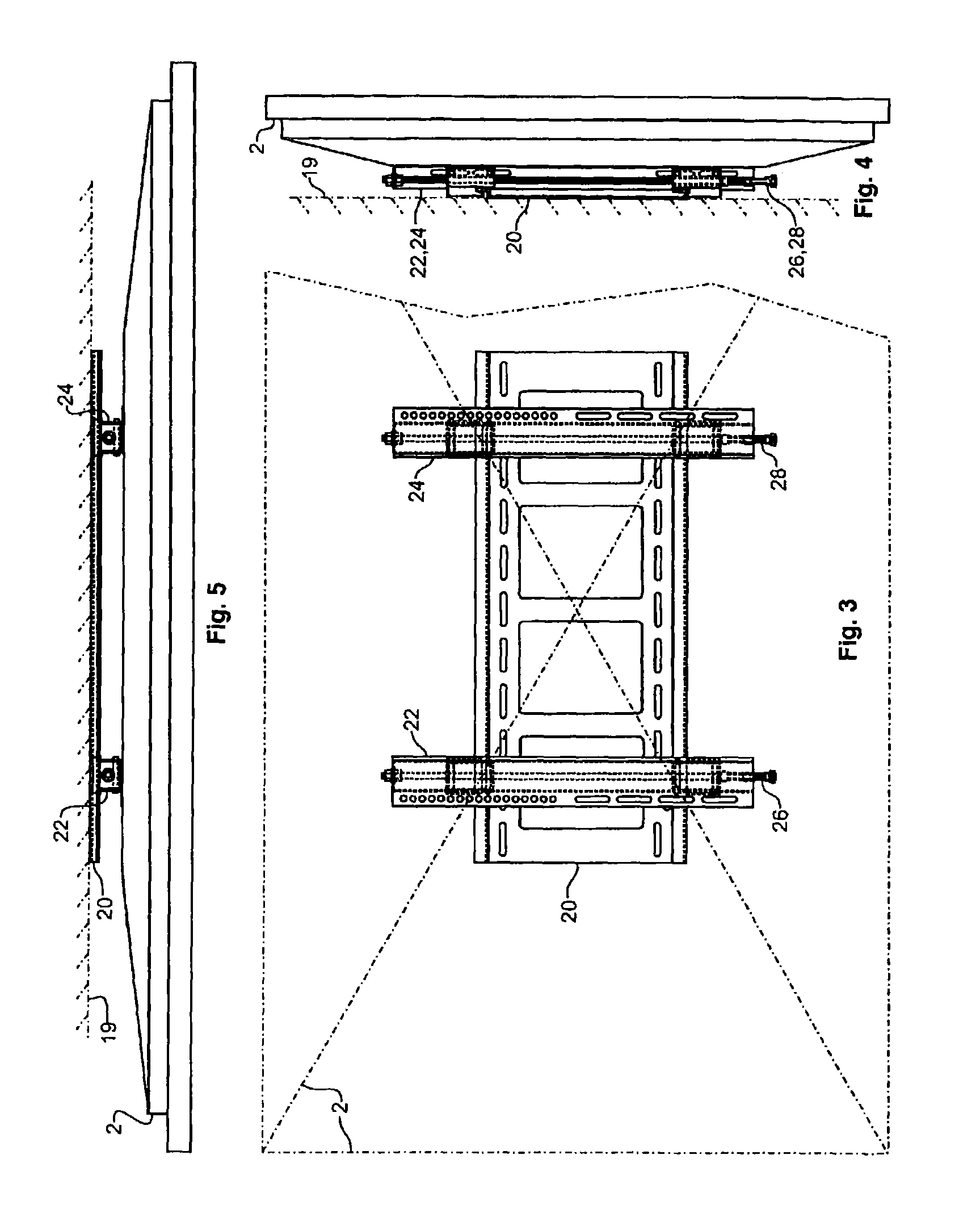
[0047]The present invention advances the art of mounting flat panel displays, such as plasmas and LCD televisions and video monitors, by teaching mounting bracket apparatus that enable adjustment of the mounted position of such displays vertically, horizontally and skew. The apparatus include wall brackets and display brackets. In use, the wall brack...


PUM


Abstract

A mounting bracket apparatus for adjustably supporting a flat panel display from a wall. The mounting bracket includes a wall bracket, a display bracket and two traversing mounts. The traversing mounts are supportively disposed between the wall bracket and the display bracket, and driven along a pair of substantially parallel linear axes by a pair of actuators enabling vertical adjustment of the display bracket. The traversing mounts are flexibly coupled between the wall bracket and the display bracket, thereby enabling misalignment of the positions to adjust the skew of the display bracket relative to the wall bracket.

Description

BACKGROUND OF THE INVENTION[0001]1. Field of the Invention[0002]The present invention relates to mounting brackets. More specifically, the present invention relates to an adjustable mounting bracket for supporting a flat panel television or display from a wall or similar surface.[0003]2. Description of the Related Art[0004]Flat panel televisions and displays are becoming increasingly common and will gradually replace virtually all cathode ray tube televisions and displays. Flat panel televisions and displays are frequently hung on a wall in a fashion reminiscent of paintings and photographs because their structures are similar. Flat panel displays are large, heavy, and expensive, and therefore the process of mounting them to a vertical surface is daunting. Installers and users who do their own installation typically avoid repetitive mounting and dismounting of a flat panel display because of the difficulty of the task and the risk of damage involved.[0005]Current flat panel display ...

Claims


Application Information

Patent Timeline
Patent Type & Authority Patents(United States)
IPC IPC(8): A47F5/00A47G1/24
CPCF16M11/18F16M13/02A47G1/16A47G1/1606A47G1/24F16M2200/025
Inventor GRAHAM, JONATHAN W.
Owner LEGRAND AV INC
Why Eureka
Try Eureka