Suspension apparatus and method for electric railway rigid contact net

A technology of electrified railway and rigid contact, which is applied in the direction of cable railway, railway vehicle, transportation and packaging, etc. It can solve the problems of heavy maintenance workload, difficult installation, complex structure, etc., and achieves convenient installation and maintenance, simple structure and low weight Effect

Inactive Publication Date: 2007-08-29
CHINA RAILWAY FIRST SURVEY & DESIGN INST GRP
View PDF9 Cites 0 Cited by
  • Summary
  • Abstract
  • Description
  • Claims
  • Application Information

AI Technical Summary

Problems solved by technology

Obviously, this structure is very complicated, and it is also very difficult to install on site, and it is not easy to adjust, and the maintenance workload is very heavy in actual operation.

Method used


Image

  • Suspension apparatus and method for electric railway rigid contact net
  • Suspension apparatus and method for electric railway rigid contact net
  • Suspension apparatus and method for electric railway rigid contact net

Examples


Embodiment Construction

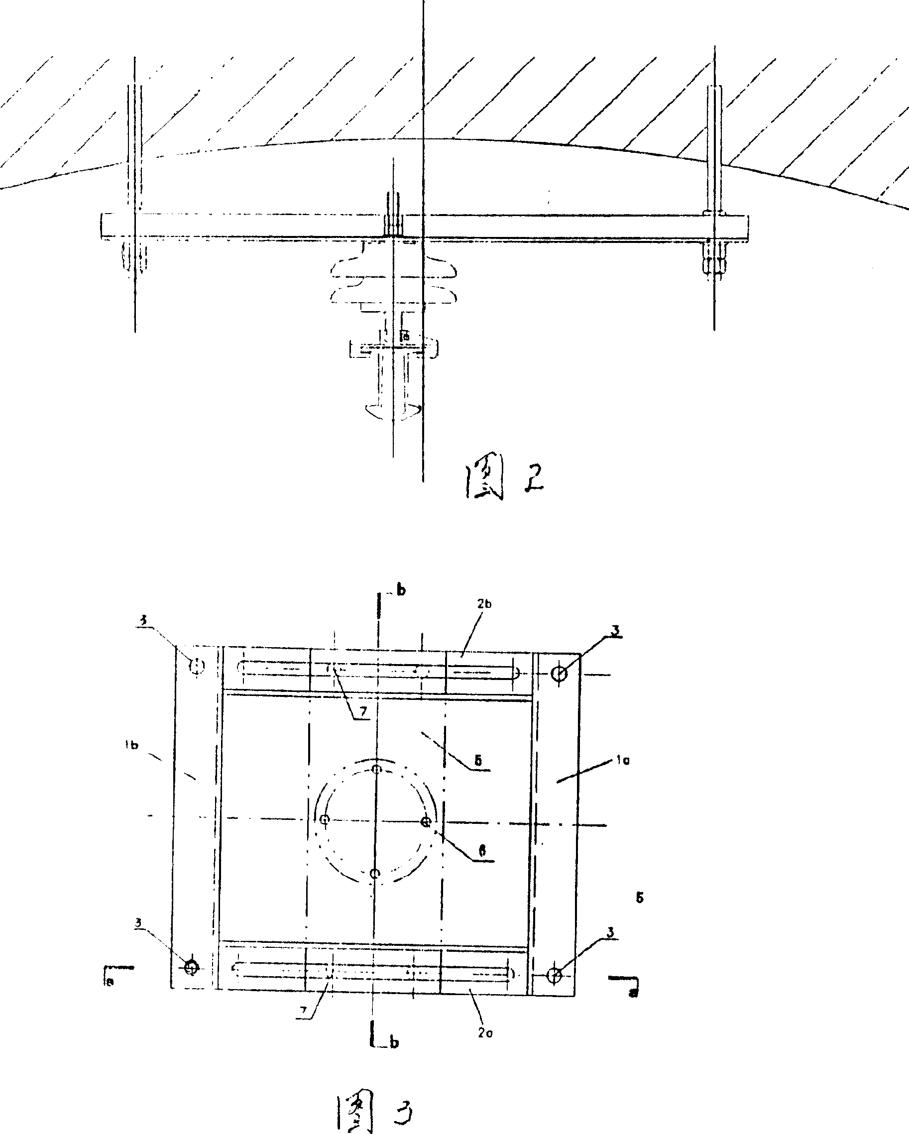
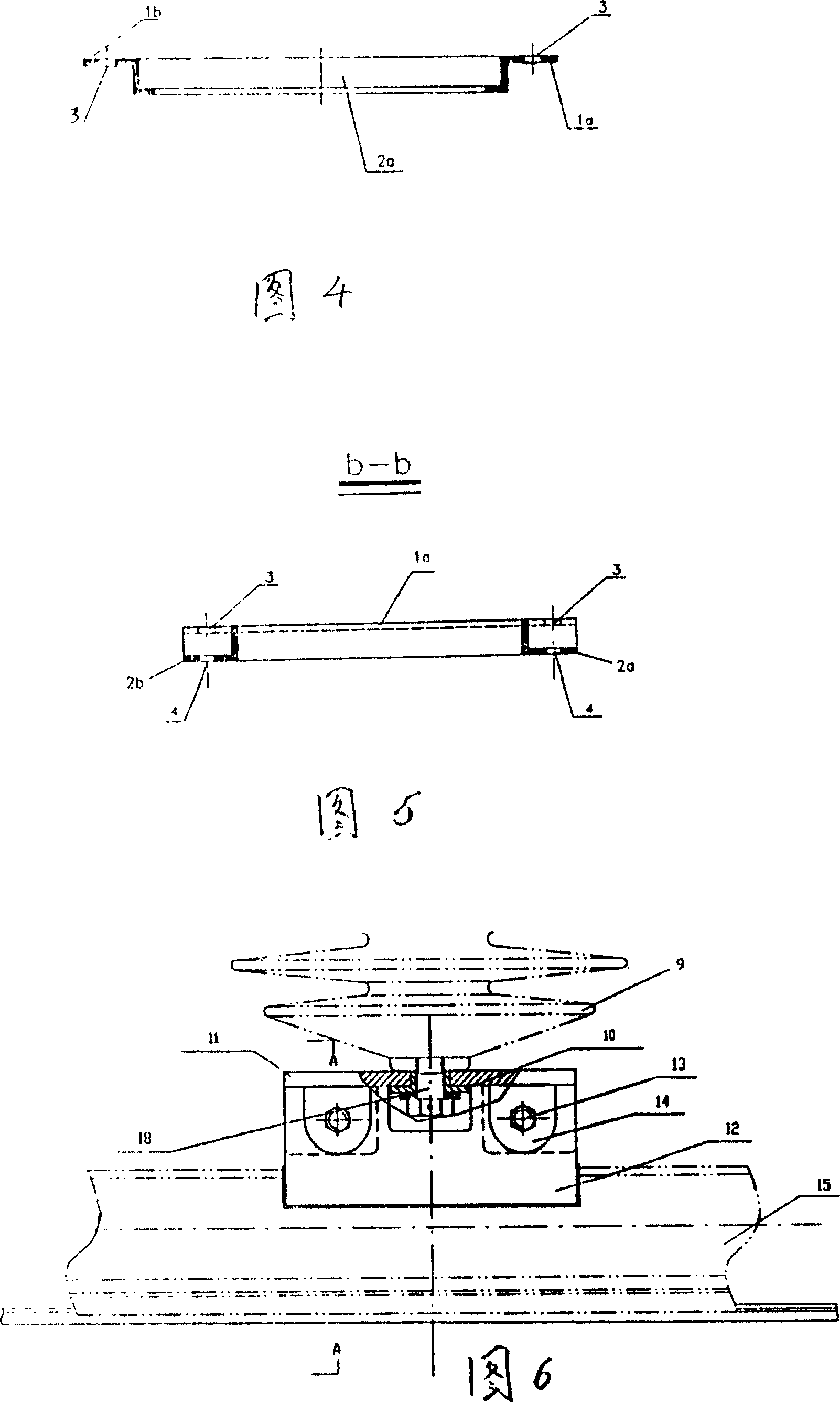
[0022] The fixed base of the present invention is shown in Fig. 3, and it is welded by two groups of angular shaped steels 1a, 1b and 2a, 2b, wherein 1a and 1b are folded upwards, and 2a and 2b are folded downwards, see Fig. 4 and Fig. 5. There are four screw holes 3 on the angle steels 1a and 1b respectively, which are used to cooperate with anchor bolts to fix the base on the tunnel roof wall. A long hole 4 is respectively opened on the angle steels 2a and 2b for fixing the connecting plate of the fixed insulator on the base. The dotted line box 5 in Fig. 3 is the insulator base for fixing the insulator, on which are provided four bolt holes 6 connected with the insulator and long bolt holes 7 for fixing it to the sides 2a and 2b of the fixed base, And because the elongated hole 7 is provided, the position adjustment can be easily carried out along the longitudinal direction of the connecting plate 5 (that is, the transverse direction of the railway track).

[0023]Refer t...


PUM


Abstract

The present invention discloses one kind of fixing device and method of the power supply line contacting electrified locomotive current collector. The fixing device has fixing pedestal of four perpendicular shaped steels in the same plane and welded into one rectangular structure, insulator holder fixed on the pedestal and insulator on the insulator holder. The present invention has simplified insulator installation and strengthens the connection strength between the insulator and the pedestal. The present invention has intermediate suspending wire holder and anchoring wire holder to fix the rigid beam, and under the action of the intermediate suspending wire holder the beam may play freely inside the wire holder. The method of arranging each beam equally inclined with the rail axle direction can solve the problem of beam in heat expanding and cold contracting and ensure the smooth powering of locomotive pantograph.

Description

technical field [0001] The present invention relates to a power line fixing device and method for contacting the collector of electrified locomotive, more precisely, it is a device for supporting or suspending catenary and its setting method. The device of the present invention includes rigid beams with a π-shaped structure, interlocking joints connecting the rigid beams, clamps for fixing the rigid beams on the insulators, insulators, a fixed base, and an insulator connection base plate for fixing the insulators on the fixed base The method of the present invention is to fix the fixed base on the tunnel roof or other fixtures, fix the insulator on the base, fix the clamp on the insulator, and then set the rigid beam on the clamp. The rigid beams of the present invention are also referred to as busbars. Background technique [0002] The power line suspension device in contact with the collector of the disclosed electrified locomotive generally adopts a chain suspension form...

Claims


Application Information

Patent Timeline
Patent Type & Authority Patents(China)
IPC IPC(8): B61B12/02B60M1/20
Inventor 马千里李晋汪吉健何廷文田志军赵玮张弘赵阼顼
Owner CHINA RAILWAY FIRST SURVEY & DESIGN INST GRP
Why Eureka
Try Eureka