Automatic control valve block of biliquid flow

An automatic control valve and control valve technology, applied in the field of hydraulic devices, can solve the problems of inability to pre-assemble and adjust, there are many seals, and the volume of the control oil cavity is large. road simple effect

Inactive Publication Date: 2007-09-12
SHANGHAI ANGFENG MINING MECHANIC & TECH CO LTD
View PDF7 Cites 0 Cited by
  • Summary
  • Abstract
  • Description
  • Claims
  • Application Information

AI Technical Summary

Problems solved by technology

[0003] The internal structure of the control valve block is shown in Figures 2 and 3. A cartridge valve composed of components arranged in rows is used, and the design is relatively flexible. Slow speed, low control sensitivity, high processing requirements, high failure rate, and cannot be pre-assembled and adjusted, it is inconvenient to replace during maintenance, the heat is large, and the working cylinder cannot be protected when it is impacted by external forces. The spool DV1, the main spool DV1a and the unloading control piston DV1b constitute the pilot unloading relief valve DV1. In order to realize the function of an integral valve in cooperation with each other, the mutual position accuracy requirements during processing Strict, not easy to process, and several control oil passages need to be drilled to transmit the control pressure. The junction of each divided valve core and the valve block body needs to be sealed with a sealing material, so as not to cause loss of control pressure and Prevent leakage of hydraulic oil, so the number of seals used is relatively large
Another example is the two-part spool of SV1 and SV1a that constitutes the hydraulic control check valve SV1, and each part is composed of several independent components. Since the ejector rod in SV1a can only transmit pressure to the main spool of SV1, it cannot transmit pressure. Pull force, in order to solve the processing and installation errors, it is necessary to leave a certain idle stroke. When the control pressure of the valve suddenly becomes small, it cannot help the main valve core to close immediately, and can only be closed by the return spring force of the main valve core. , so the action speed is slow, and sometimes the phenomenon of hydraulic flutter occurs. In order to prevent this phenomenon, an adjusting screw is used to solve the problem by adjusting the opening degree of the main valve core (throttling), but the liquid during normal operation is increased. resistance, also increases heat

Method used


Image

  • Automatic control valve block of biliquid flow
  • Automatic control valve block of biliquid flow
  • Automatic control valve block of biliquid flow

Examples


Embodiment 1

[0026] Embodiment 1: The control valve block 5 of the present invention is applied to a hydraulic grab.

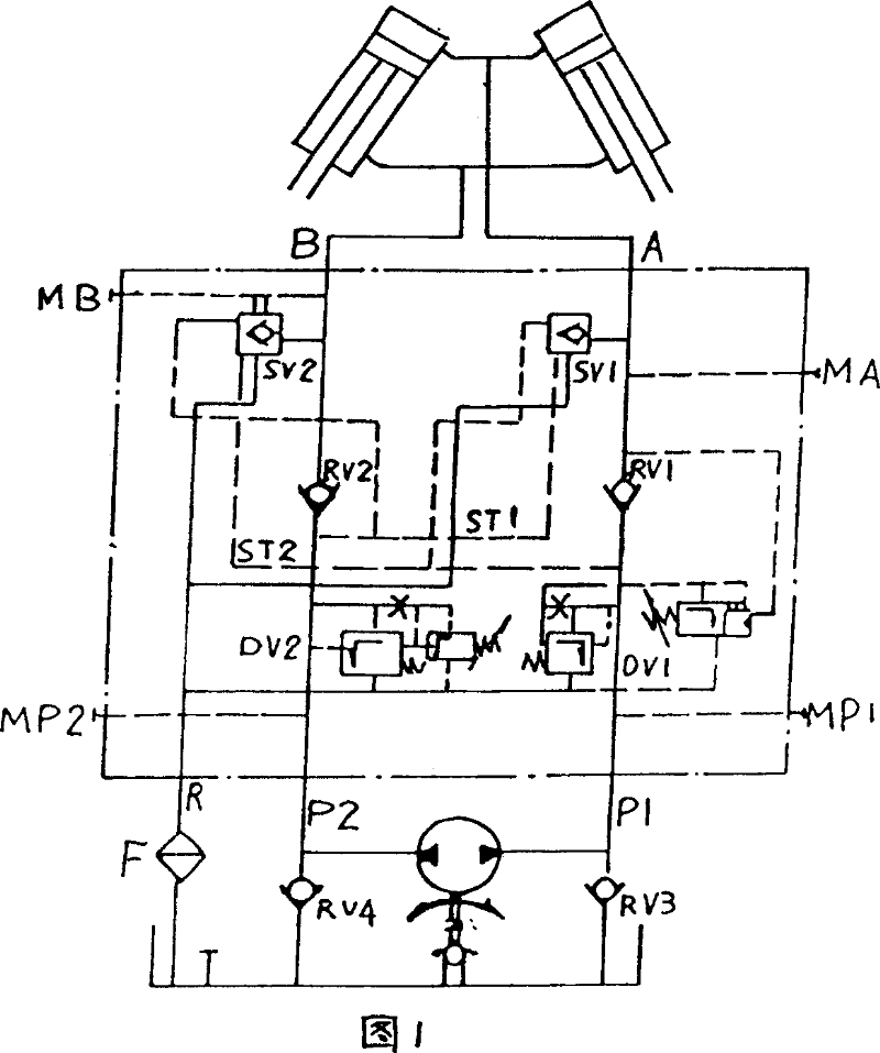
[0027] As shown in Figure 9, the hydraulic grab generally consists of an electric motor 1, a two-way hydraulic pump 2, two oil suction check valves 3 directly mounted on the oil suction port of the two-way hydraulic pump, an oil return filter 4, and an oil return filter 4 of the present invention. The control valve block 5, at least one oil cylinder 6 (the number of oil cylinders is the same as the number of claws), and hydraulic components such as oil pipes, joints, and oil tanks for connection. The hydraulic control principle is shown in Figure 10.

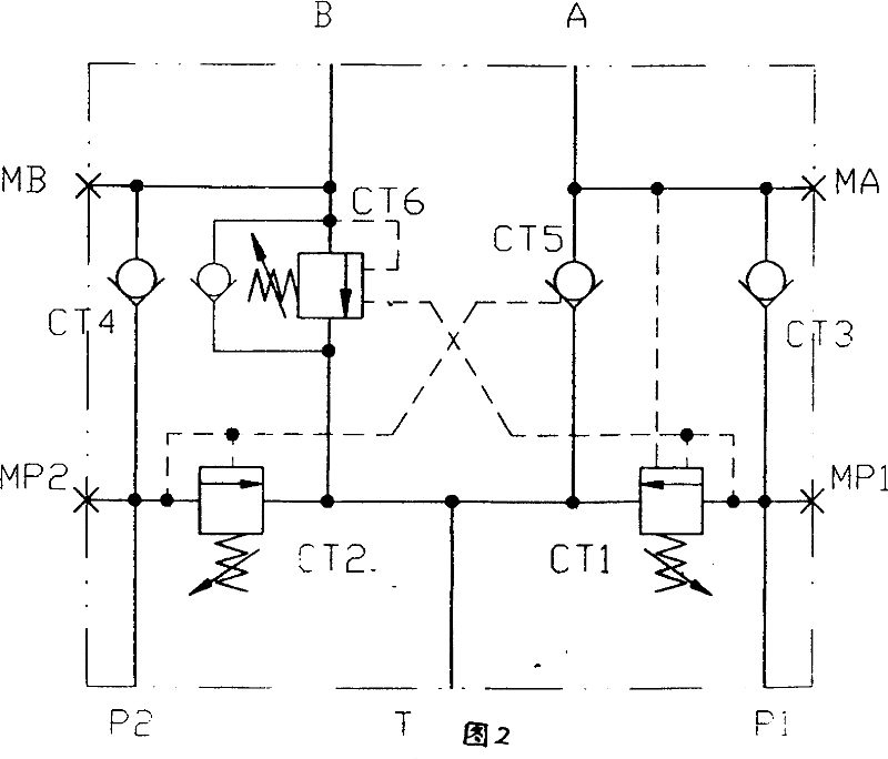
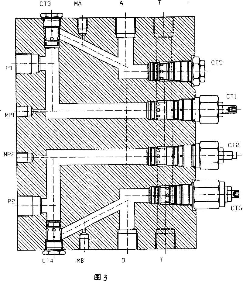
[0028]The control valve block 5 consists of a valve body 11, a pilot unloading relief valve CT1, a pilot relief valve CT2, two check valves CT3 and CT4, a hydraulic control check valve CT5, and a load holding valve CT6. Composed of six valve parts, there are five external main oil ports on the valve body 11, which are two o...

Embodiment 2

[0033] Embodiment 2: The control valve block 5 of the present invention can also be applied to the opening and closing device of the port spreader, and the starting device of the port and inland river sluice. The control method is similar to the hydraulic grab, except that the object is changed from the paw to the gate. and other devices, the hydraulic control principle is shown in Figure 9, which is consistent with the hydraulic grab and will not be repeated.

Embodiment 3

[0034] Embodiment 3: The control valve block 5 of the present invention is applied to drilling machinery to drive drill bits, and is applied to rotary machinery such as construction machinery chassis. The hydraulic control principle is shown in FIG. 10 .

[0035] The hydraulic power supply and control method used to drive the drill bit on drilling machinery basically adopts the method of one-way hydraulic pump and reversing valve. After adopting the hydraulic control principle shown in Figure 10, the purpose of working process control such as drill bit drilling and reverse replacement of drill rods can be achieved by changing the direction of the motor. The control principle inside the control valve block 5 is shown in FIG. 9 . The difference is that the oil port B is used as the power oil port for normal drilling, providing a lower working protection pressure, and the oil port A is used as the power oil source port for dismantling the drill pipe, which can provide an oil sour...


PUM


Abstract

The invention relates to a double-fiow autocontrol valve comprises a valve body and a control valve assembly having at least a group of the control valve members, which comprises a relief valve, a non-return valve and a liquid-control non-return valve. The main oil mouth comprises an oil inlet, a working oil mouth and a oil return mouth. The oil inlet is connected separately with the non-return valve and the relief valve. The outlet of the non-return valve is connected separately with the working oil mouth and liquid-control non-return valve. The oil-recovery of all the valves is connected with the oil inlet.

Description

technical field [0001] The present invention relates to the field of hydraulic control, in particular to a hydraulic grab used for various cranes, a hydraulic device used for engineering machinery, mines and port equipment, and a hydraulic grab used for petroleum and geological drilling equipment. The dual liquid flow automatic control valve block in the device. Background technique [0002] The current hydraulic grab uses a power cable to drive the motor forward and reverse to drive a two-way hydraulic pump, and uses two directions of hydraulic oil sources (double fluid flow) to complete the hydraulic power supply of the hydraulic grab and alternately control the grab opening. The problem of closing and closing reduces the problems of many accessories and high failure rate of the control part brought by external control to the equipment. The principle of automatic control of the two-way hydraulic pump is shown in Figure 1. The main components include DV1 pilot type unloadin...

Claims


Application Information

Patent Timeline
Patent Type & Authority Patents(China)
IPC IPC(8): F15B13/02
Inventor 钱鸣朱宏敏
Owner SHANGHAI ANGFENG MINING MECHANIC & TECH CO LTD
Why Eureka
Try Eureka