Supercharge Your Innovation With Domain-Expert AI Agents!

Electric cable protector in cable pipeline

A technology of wire retainer and cable duct, which is applied in the direction of electrical components, etc., can solve the problems of reducing the reliability of device retention, and the strength cannot be increased.

Inactive Publication Date: 2007-09-19
APALINLAJE ELECTRONICS
View PDF3 Cites 0 Cited by
  • Summary
  • Abstract
  • Description
  • Claims
  • Application Information

AI Technical Summary

Problems solved by technology

[0003] The purpose of these existing retainer devices is to prevent the wires from falling out of the cable duct when the retainer top cover is removed from the cable duct to handle the wires. These retainer devices have such Or the disadvantage of that: when a new wire is to be inserted into the wire harness, the new wire must be screwed through the retainer device when the retainer device is of the closed type; where the retainer device is open, the Channels reduce the reliability of device retention; and in all cases, these devices are only connected to the bottom wall of the cable duct, whereby their strength cannot be obtained because they do not bond the cable duct walls together. Increase

Method used


Image

  • Electric cable protector in cable pipeline
  • Electric cable protector in cable pipeline
  • Electric cable protector in cable pipeline

Examples


Embodiment Construction

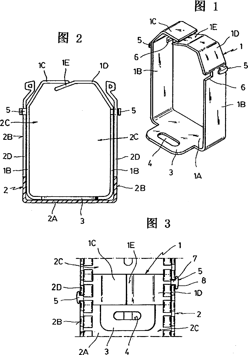
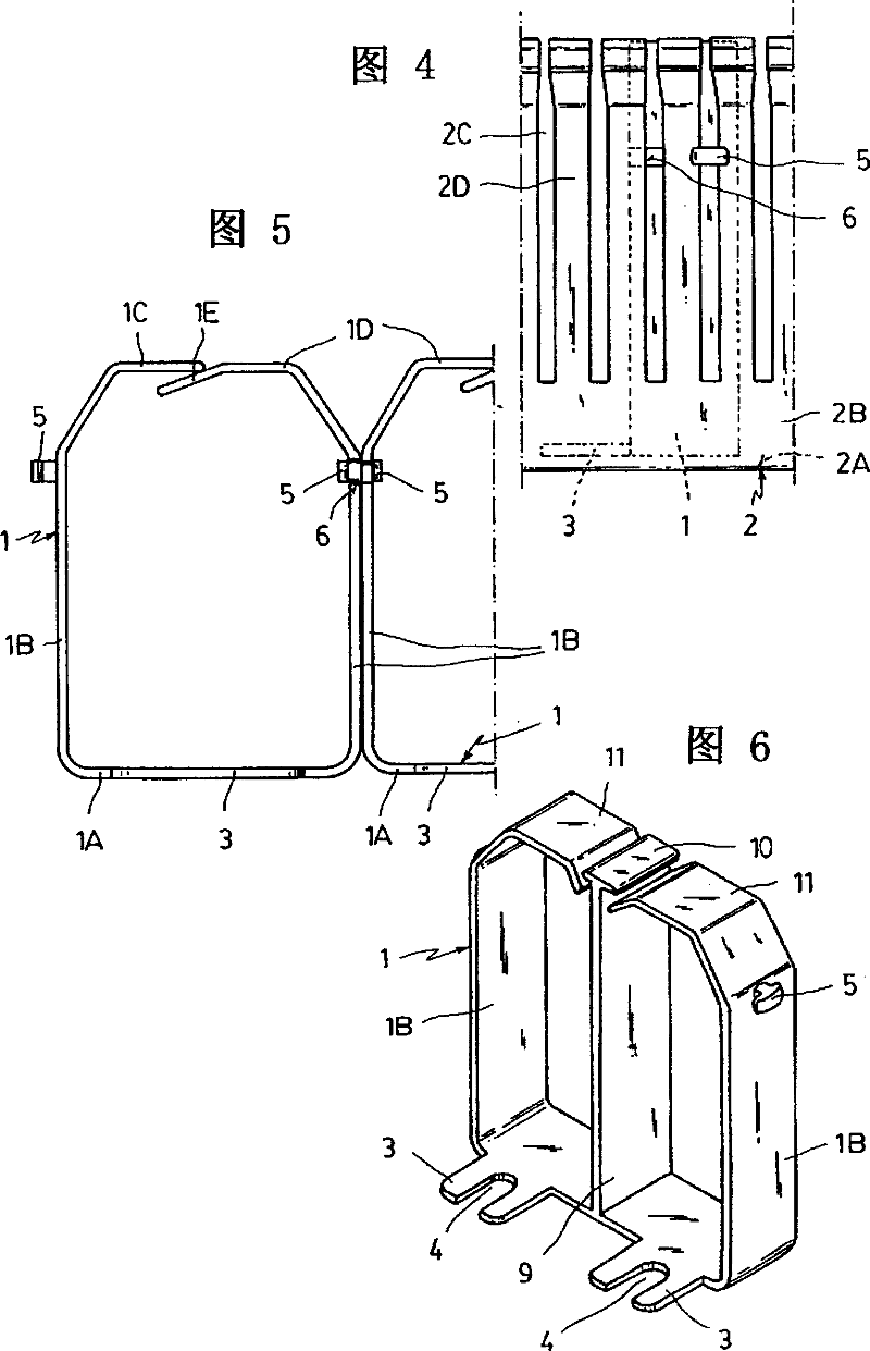
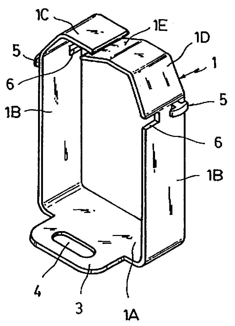
[0019] As shown in Figure 1, the retainer device according to the invention consists of an open narrow ring 1 with a regular prismatic profile, the walls of which correspond to the U-shaped base of the cable duct for which it is intended Internal section of part 2.

[0020] The open narrow ring 1 comprises a base 1A, two identical wall portions 1B and two free end portions 1C and 1D, all of which match the internal shape of said base portion 2 .

[0021] The bottom 1A has means for connecting the bottom wall 2A of the cable duct base 2, which consists of at least one transverse fin-shaped extension 3 having an elongated hole 4 and being able to pass through the bottom of the cable duct base 2 Wall 2A secures the holder device to a support surface (not shown in the figure).

[0022] The two wall portions 1B are engaged with the inner surface of the wall 2B of the cable duct base portion 2, the wall 2B being formed with narrow grooves 2C and transverse fins or strips 2D, and ha...


PUM


Abstract

A retainer device for conductors in an electrical raceway, which is applicable mainly to raceways formed by the association of a U-shaped base section (2) with a cover section, in which the base section (2) is provided in the walls thereof with equal equidistant narrow transverse slots which define therebetween outstanding transverse tabs or strips which form a comb-like arrangement. The device is formed by an open narrow annular member (1) of right prismatic profile, the bottom portion whereof corresponds to the right internal cross section of the base section (2), of the raceway to which it is directed. The member (1) has a bottom portion (1A), two wall portions (1B) and two free end portions (1C, 1D), where the two free end portions (1C, 1D) are located at the level of the open side of the base section, are facing each other in overhanging fashion and are partly overlapping, at the same time as the two wall portions (1B) are provided with projections for interacting with the walls and / or with the wall portion (1B) of an adjacent member.

Description

technical field [0001] The present invention relates to a wire retainer device in a cable duct, in particular to a retainer device capable of retaining wires in a bundle, the wires being accommodated in a cable duct defined by a defined side wall and Formed by a U-shaped base portion of a bottom wall and a flat top cover portion connected to the U-shaped base portion, the base portion being provided in the wall of the duct with equally spaced transverse grooves defining fins therebetween , the fins collectively form a comb configuration. The invention also relates to how to use a retainer according to the invention. Background technique [0002] Devices are known for retaining a bundle of electrical wires in a cable duct having imperforate walls. This retainer is only connected to the bottom wall of the duct and has means for accommodating longitudinal distribution members, such as those disclosed in Spanish Utility Model No. 196,298, wherein the retainer means are enclose...

Claims


Application Information

Patent Timeline
Patent Type & Authority Patents(China)
IPC IPC(8): H02G3/04
CPCH02G3/0437H02G3/0418
Inventor 胡安·曼努埃尔·贝尼托·纳瓦索
Owner APALINLAJE ELECTRONICS
Features
  • R&D
  • Intellectual Property
  • Life Sciences
  • Materials
  • Tech Scout
  • Unparalleled Data Quality
  • Higher Quality Content
  • 60% Fewer Hallucinations
Learn More