Machine for processing printed circuitboard

A technology for printed circuit boards and processing machines, which is used in printed circuits, metal processing machinery parts, metal processing, etc., and can solve problems such as reduced processing speed, damage to linear guides, and incomplete removal of chips.

Inactive Publication Date: 2007-10-10
HITACHI SEIKO LTD
View PDF5 Cites 0 Cited by
  • Summary
  • Abstract
  • Description
  • Claims
  • Application Information

AI Technical Summary

Problems solved by technology

However, the generated chips, etc. cannot be completely removed
Therefore, the chips generated by the machining are attached to the linear guide, and the machining speed may be reduced.
[0012] In addition, attached chips, etc. may damage the linear guide and reduce the machining accuracy.

Method used


Image

  • Machine for processing printed circuitboard
  • Machine for processing printed circuitboard
  • Machine for processing printed circuitboard

Examples


Embodiment Construction

[0023] Hereinafter, the present invention will be described with reference to the illustrated embodiments.

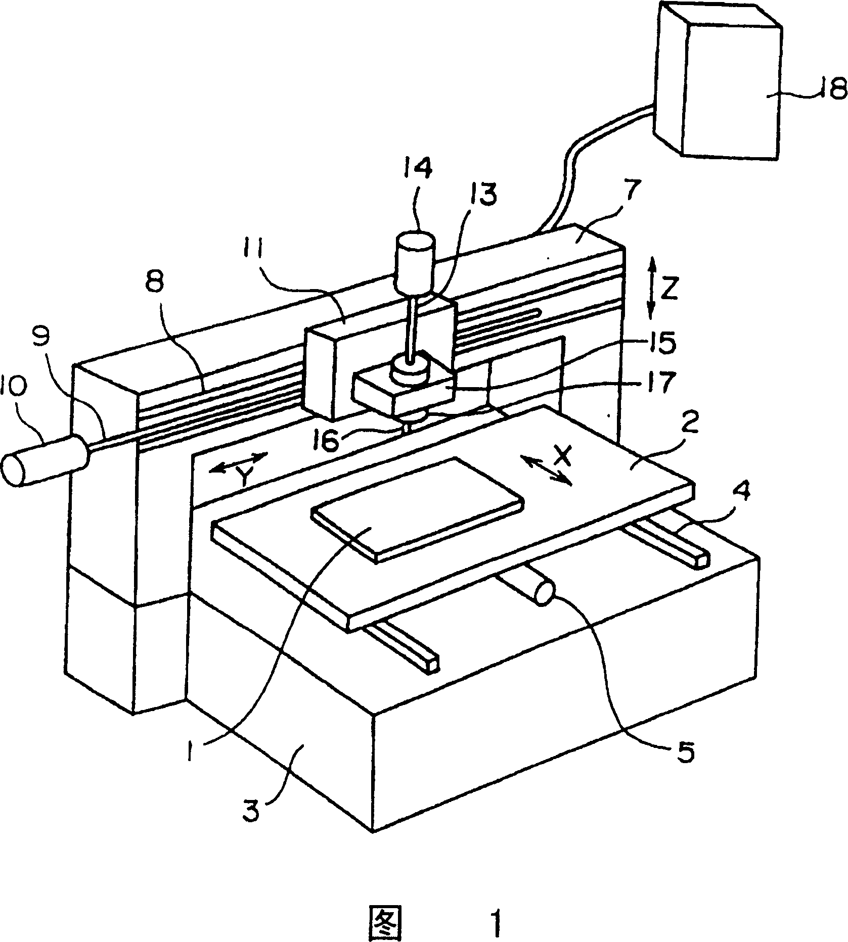
[0024] FIG. 1 is a perspective view of a printed wiring board processing machine according to the present invention, and components that are the same or have the same function as those in FIG. 6 are denoted by the same symbols and descriptions thereof are omitted. In this figure, a printed wiring board 1 is fixed on a table 2 . The table 2 can move freely in the front-back (X) direction on a pair of linear guides 4 fixed to the base 3 . The motor 5 positions the table 2 in the X direction.

[0025] The portal type transverse guide rail 7 straddles the workbench 2 and is fixed on the base 3 . The lateral slide plate 11 is movable in the left and right (Y) directions on a pair of linear guides 8 fixed to the portal rail 7 . The motor 10 and the rolling screw 9 position the transverse slide 7 in the Y direction.

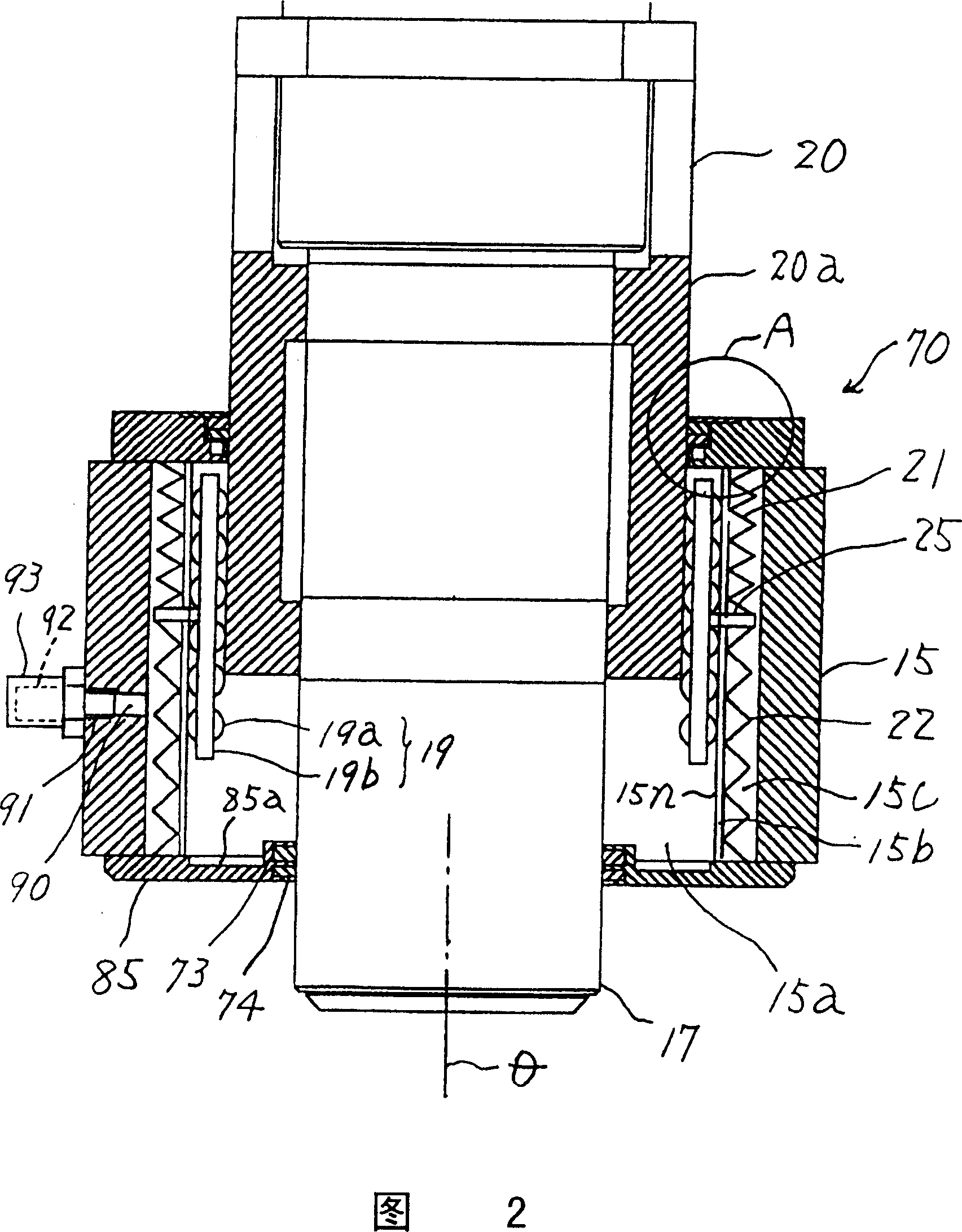
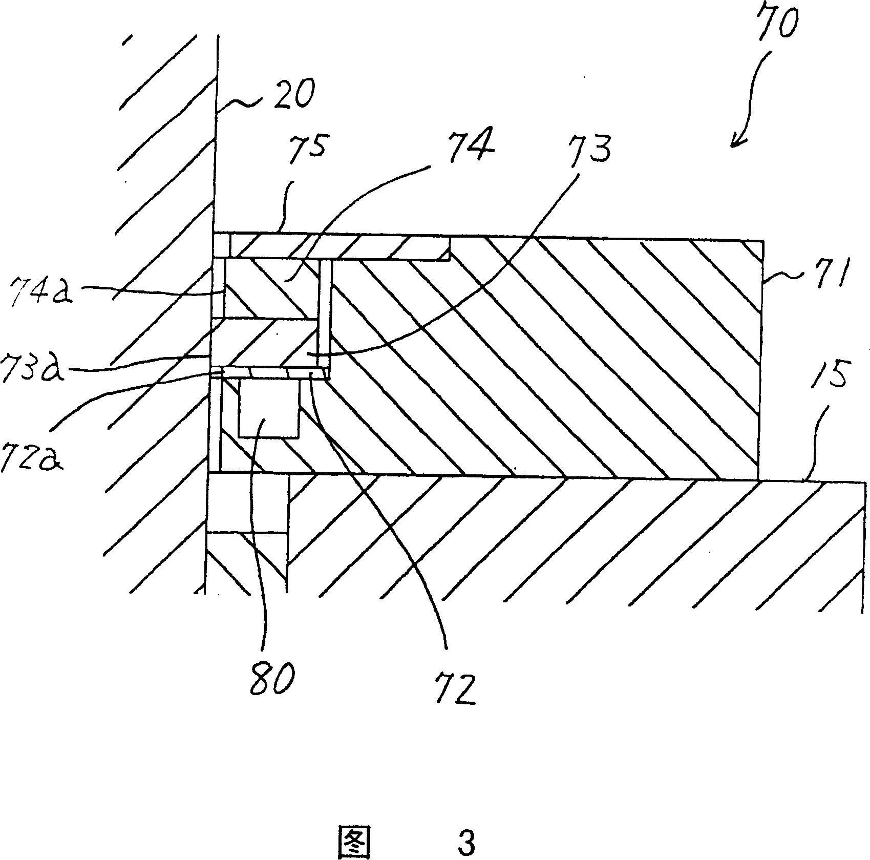
[0026] A motor 14 and a tool rest (carriage) 15 are fix...


PUM


Abstract

A machine for machining the printed circuit board features that its mainshaft and shaft sleeve are integrally supported, the straight line guider constituted by the holder of roller can freely move up and down in tool carrier, a sealing unit composed of soft scraper and duster is arranged above said tool carrier, and the lower cover holding soft scraper and duster is arranged under said tool carrier. It can prevent the cuttings from coming in tool carrier.

Description

technical field [0001] The present invention relates to a printed circuit board processing machine which positions a main shaft rotatably holding a tool in a horizontal direction by a tool holder, and moves the main shaft in the axial direction of the tool for processing. Background technique [0002] Fig. 6 is a sectional view of main parts showing a first spindle unit of a conventional printed wiring board processing machine. [0003] In this figure, the spindle 17 is fixed on the tool holder 15 . A motor (not shown) is provided inside the spindle 17 to drive the drill 16 held at the tip to rotate. The tool rest 15 is guided vertically by a guide rod 52 via a guide bearing 51 . The two ends of the guide rod 51 are interposed between the support plates 53 and are fixed on the transverse slide plate 11 . The horizontal sliding plate 11 is free to move in a direction perpendicular to the paper surface. The nut 54 fixed on the knife rest 15 is screwed on the thread rolling...

Claims


Application Information

Patent Timeline
Patent Type & Authority Patents(China)
IPC IPC(8): B23Q11/08B26D1/06H05K1/00
Inventor 本田勇二伊藤靖大谷民雄
Owner HITACHI SEIKO LTD
Why Eureka
Try Eureka