Button switch

A switch and button technology, applied in the direction of electric switch, key key mechanism, emergency connection, etc., can solve problems such as obstructing the thinning of button switches, poor operation feeling, deviation of operation amount, etc., and achieve cost reduction and thinning. , the effect of a good sense of operation

Inactive Publication Date: 2007-10-31
ALPS ALPINE CO LTD
View PDF0 Cites 2 Cited by
  • Summary
  • Abstract
  • Description
  • Claims
  • Application Information

AI Technical Summary

Problems solved by technology

[0013] However, in the structure of the conventional push button switch, since the cover body is mounted on the housing by the arm portion and the locking portion provided in the front and rear directions along the operating direction of the operating member, when the operating portion of the operating member slides on the inclined piece, At this time, the cover with the inclined piece tends to float up to the side opposite to the direction in which the movable contact is pressed, and as a result, a deviation in the amount of operation relative to the operation member is likely to occur in the reversed position of the movable contact, and the operation feeling may change. Poor, so there is a problem that hinders the thinning of the push button switch

Method used


Image

  • Button switch
  • Button switch
  • Button switch

Examples


Embodiment Construction

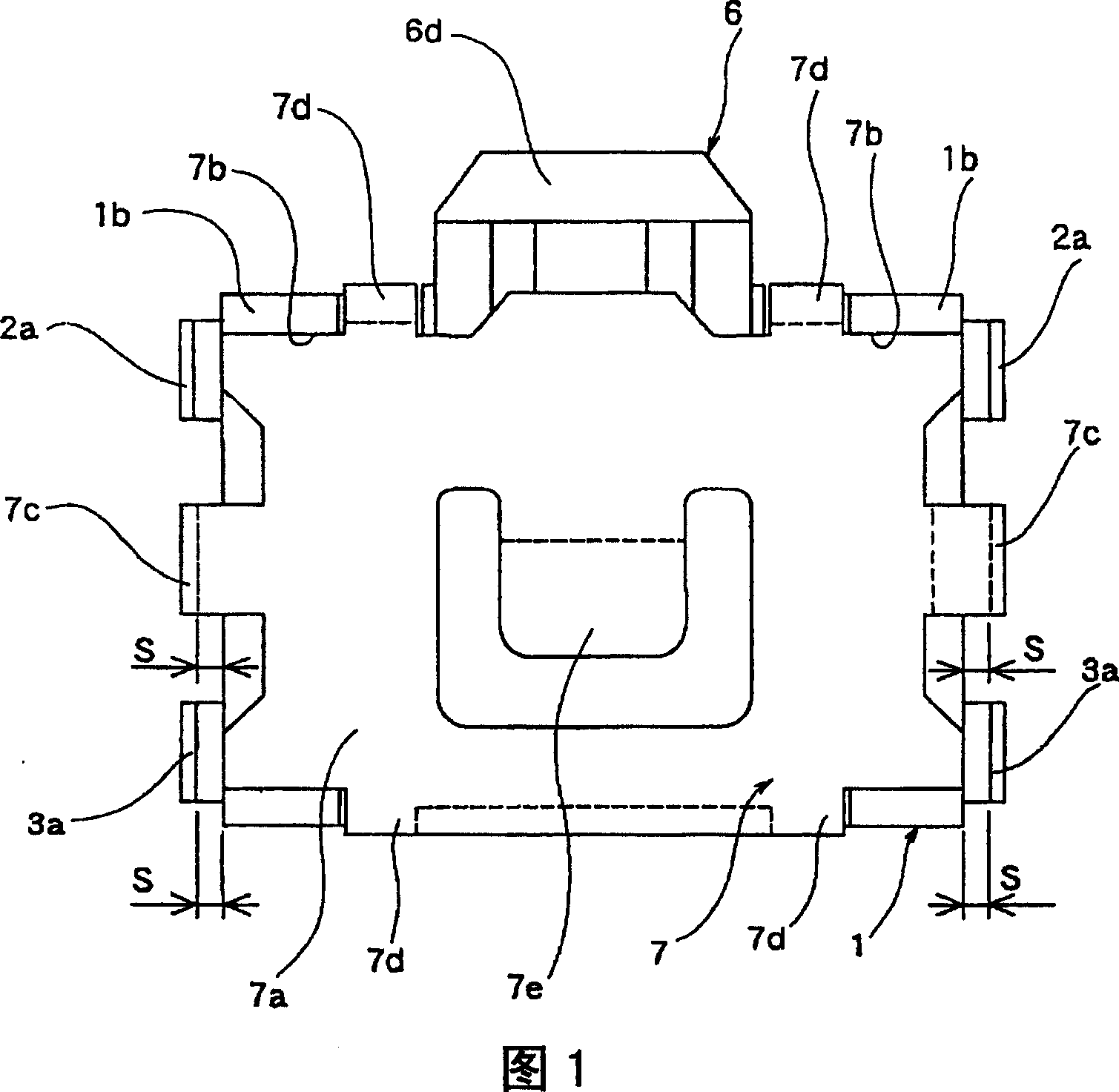
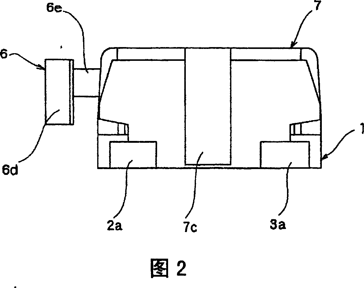
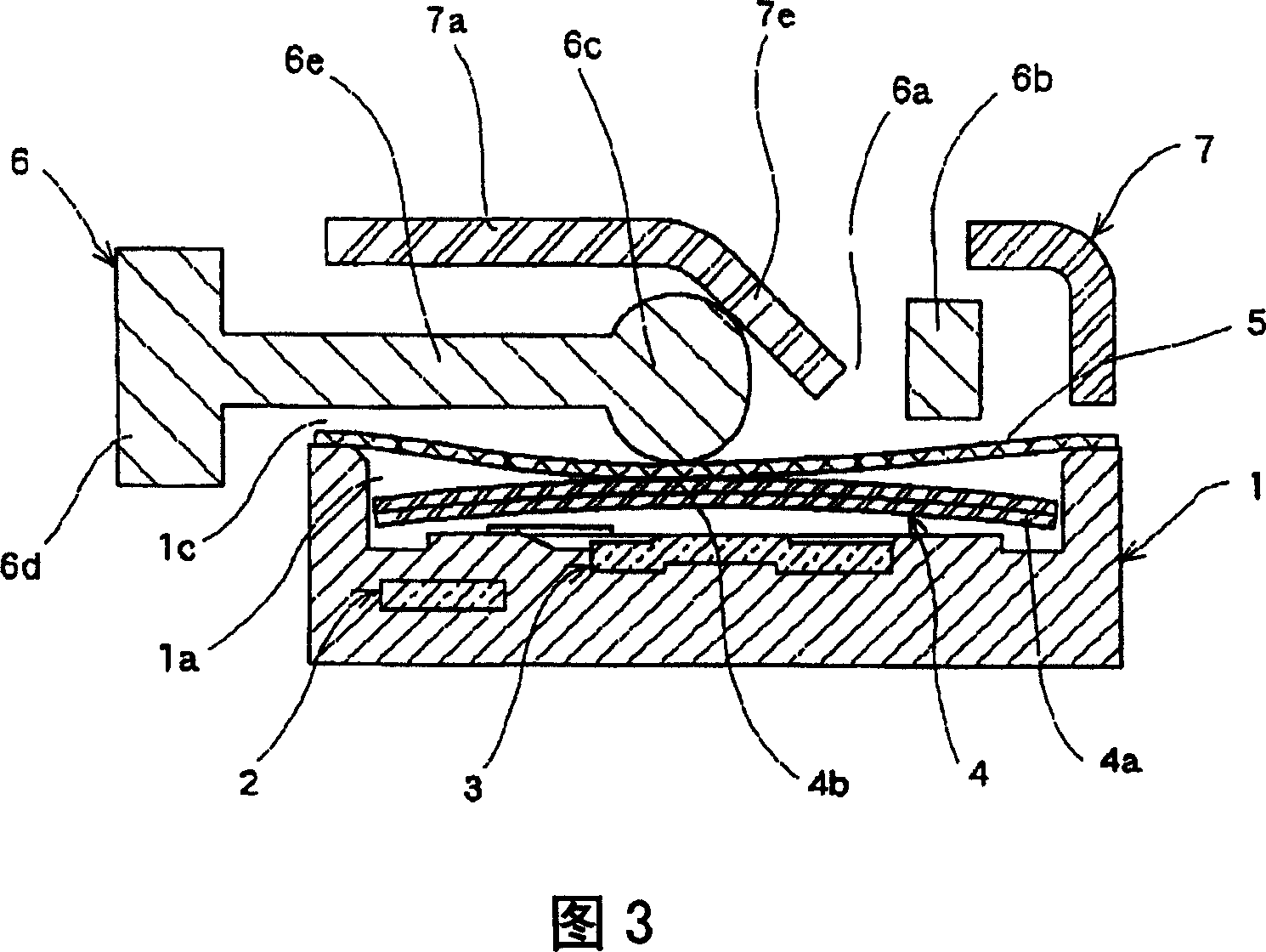
[0041] Embodiments of the push button switch of the present invention are shown below in FIGS. 1 to 9 . Fig. 1 is a top view of the push button switch, Fig. 2 is a side view of the push button switch, Fig. 3 is a sectional view of main parts of the push button switch, Fig. 4 is a sectional view of main parts when the push button switch is pressed, Fig. 5 is a top view of the housing, Fig. 6 is a side view showing the state where the push button switch is soldered and mounted on the surface mount substrate, FIG. 7 is a side view showing the state where the legs of the cover are widened and soldered, and FIG. As a plan view of the state where the ribs are formed, FIG. 9 is a side view showing the locking portion provided on the leg portion of the cover.

[0042] As shown in Fig. 1 to Fig. 3 and Fig. 5, the push button switch of this embodiment consists of a housing 1 with a storage portion, a pair of fixed contacts 2, 3 arranged facing the inner bottom surface of the storage por...


PUM


Abstract

This invention provides a push-button switch capable of having an excellent operation feeling, while being thinned. The push-button switch comprises a housing 1 with a housing part 1a, fixed contacts 2, 3 arranged on inside bottom surface of the housing part 1a, a moving contact 4 arranged on the fixed contacts 2, 3, an operation member 6 having a press part 6d projecting from a side part of the housing 1, and an operation part 6c, and a cover body 7 mounted on upper surface of the housing 1, and having an inclined piece 7e cut and raised inside the housing part 1a. Pressing operation of the press part 6d causes the operation part 6c to slide on the inclined piece 7e to bend downwardly to press the moving contact 4. A deformation prevention part is formed to prevent the cover body 7 having the inclined piece 7e from inflating in a direction opposite to the moving contact 4 in the housing part 1a, during pressing operation of the operation member 6.

Description

technical field [0001] The present invention relates to a push button switch used as an operation switch of various electronic devices, and particularly relates to a thin horizontal push button switch. Background technique [0002] As a structure of a conventional push button switch, there is known a push button switch (refer to Japanese Utility Model Registration No. 2572590), that is, a slant piece is cut into the casing from the cover body and faces the movable contact, and is sandwiched between The operating member having an elastic operating portion between the inclined piece and the movable contact, is pressed by the pressing portion to slide the operating portion on the inclined piece and press the movable contact to switch the contact. [0003] Next, the structure of a conventional push button switch will be described with reference to the drawings. [0004] FIG. 10 is an exploded perspective view of a conventional push switch, and FIG. 11 is a cross-sectional view ...

Claims


Application Information

Patent Timeline
Patent Type & Authority Patents(China)
IPC IPC(8): H01H13/52H01H13/20H01H13/04
CPCH01H13/14H01H13/48H01H13/52H01H2207/02H01H2209/016H01H2237/004
Inventor 佐藤秀隆
Owner ALPS ALPINE CO LTD
Why Eureka
Try Eureka