Apparatus and method for video signal recording/reproducing

A technology of video signal and reproduction equipment, which is applied in the direction of digital recording/reproduction, record carrier editing, color TV parts, etc., and can solve the problems of low-quality reproduction video images, etc.

Inactive Publication Date: 2007-12-26
PANASONIC CORP
View PDF5 Cites 0 Cited by
  • Summary
  • Abstract
  • Description
  • Claims
  • Application Information

AI Technical Summary

Problems solved by technology

Thus, viewers continue to see reproduced video images with low quality

Method used


Image

  • Apparatus and method for video signal recording/reproducing
  • Apparatus and method for video signal recording/reproducing
  • Apparatus and method for video signal recording/reproducing

Examples


no. 1 example

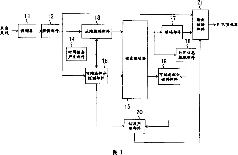
[0032] FIG. 1 is a block diagram showing the configuration of a video signal recording / reproducing apparatus according to a first embodiment of the present invention. The video signal recording / reproducing device of this embodiment includes a tuner 11, a demodulation unit 12, a compression encoding unit 13, a time information generation unit 14, a hard disk drive 15 as a storage device, a shrinkable portion detection unit 16, and a decoding unit 17 , a time information extracting unit 18 , a shrinkable part identifying unit 19 , a switching judging unit 20 and an output switching unit 21 .

[0033] The tuner 11 selects any channel from the TV signals received by the antenna. The demodulation section 12 demodulates the TV signal of the channel selected by the tuner 11 and outputs a received video signal including a digital image signal and a digital sound signal. Compression encoding section 13 performs image / sound compression encoding such as MPEG (Moving Picture Experts Grou...

no. 2 example

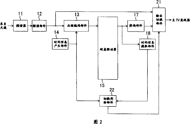
[0048] Fig. 2 is a block diagram showing the configuration of a video signal recording / reproducing apparatus according to a second embodiment of the present invention. By omitting the reducible portion detection section 16 and the reducible portion identification section 19 from the video signal recording / reproducing apparatus of the first embodiment, and including the switching judging section 22, the configuration that the video signal recording / reproducing apparatus of this example has can be obtained . Hereinafter, the switching judging section 22 will be described in detail.

[0049] The switching judging part 22 receives the time information to be superimposed on the received video signal from the time information generating part 14, and the time information extracted for the reproduced video signal from the time information extracting part 18, and performs logic judgment based on these time information, for control The output switching section 21 generates a video imag...
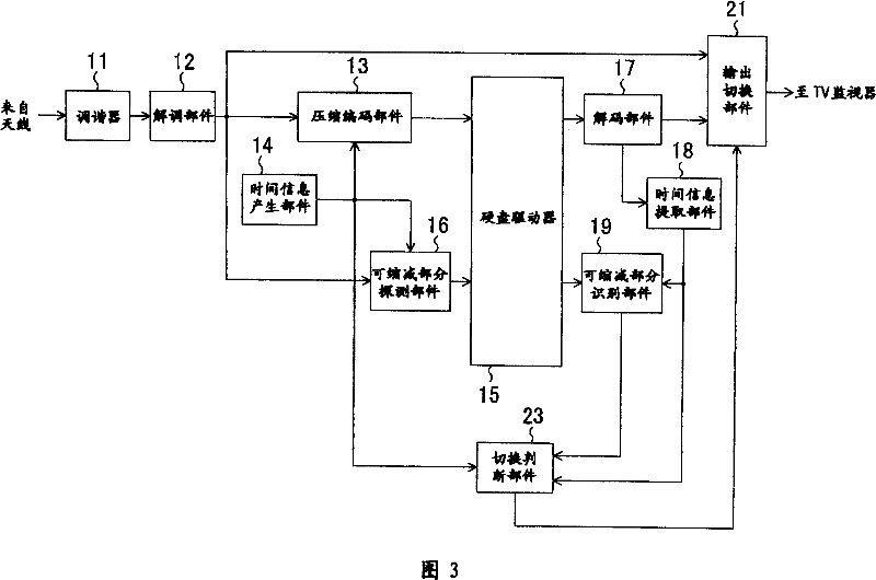
no. 3 example

[0054] According to the first embodiment, when the reproduced video signal and the received video signal belong to the same scalable section, the output is switched from the reproduced video signal to the received video signal. Therefore, the main body of the show is not cut. However, if the received video signal fades even slightly from a commercial video image, the output will not switch until the next commercial video image.

[0055] On the other hand, according to the second embodiment, once the reproduced video signal is very close to the received video signal, the output is switched. However, there may be situations where the output is switched into some other section than the collapsible section ie in the middle of the main body of the program. This goes against the viewer's desire to enjoy the main body of the program and is therefore not optional.

[0056] Then, as a third embodiment of the present invention, a video signal recording / reproducing apparatus for perfor...


PUM


Abstract

In a video signal recording / reproducing apparatus capable of outputting as a reproduced video signal a video signal which has been recorded in advance, a cuttable portion detection section detects a cutting portion in the received video signal while recording a received video signal. A cuttable portion identification section identifies whether or not a reproduced video signal reproduced from a storage device belongs to the cuttable portion detected by the cuttable portion detection section. A switch judgment section receives a result of detection by the cuttable portion detection section and a result of identification by the cuttable portion identification section, and gives an output switch section an instruction to switch a video signal to an output switching section when the switch judgment section judges that the reproduced video signal and the received video signal are contained in the same cuttable portion.

Description

technical field [0001] The present invention relates to a video signal recording / reproducing apparatus, and more particularly, to a video signal recording / reproducing apparatus in which compressed stream data obtained by performing compression encoding on a TV signal received in a storage device is recorded At the same time, the recorded compressed stream data is reproduced, and the reproduced video signal is output, that is, a video signal recording / reproducing apparatus capable of performing so-called time shift reproduction. Background technique [0002] Fig. 4 is a block diagram showing the configuration of a known video signal recording / reproducing apparatus. In this known video signal recording / reproducing apparatus, the system controller 101 performs signal control according to an operation instruction input by the viewer from the operation panel 108, switching between two signals, one signal is reconciled through the tuner 103 The tuner 104 processes the received vi...

Claims


Application Information

Patent Timeline
Patent Type & Authority Patents(China)
IPC IPC(8): H04N5/76H04N5/91H04N5/93G11B20/10G11B27/034G11B27/10H04N5/781H04N9/804
CPCH04N5/76H04N5/781H04N9/8042
Inventor 芝田英明
Owner PANASONIC CORP
Why Eureka
Try Eureka