

Screen, rear projector, projection system, and image display unit
A screen and image display technology, which is applied in the field of rear projection projectors, screens, projection systems and image display devices, can solve problems such as blurred images, achieve the effects of reducing flicker, suppressing noise, and reducing energy consumption parts
- Summary
- Abstract
- Description
- Claims
- Application Information
AI Technical Summary
Problems solved by technology
Method used
Image

Examples
Embodiment approach 1
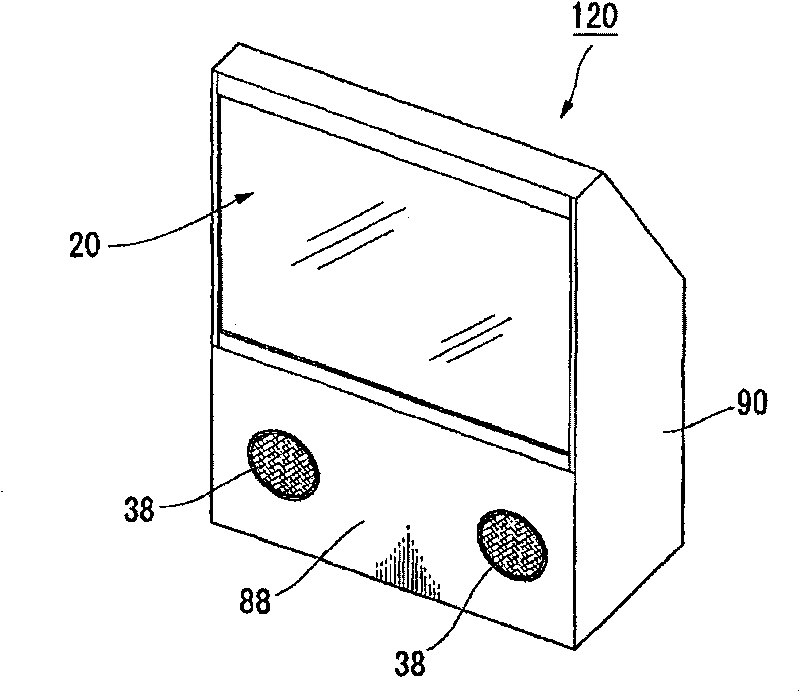
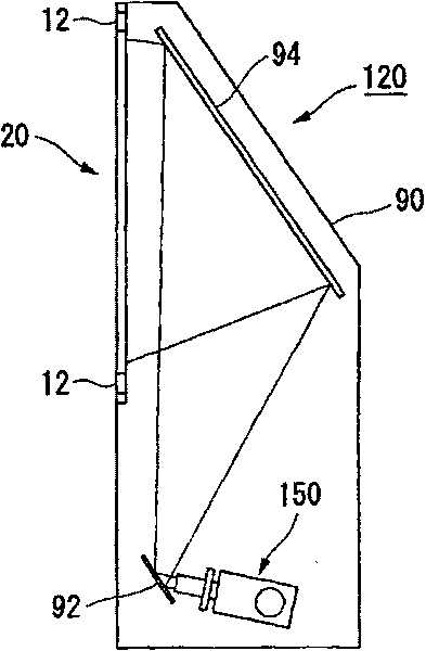
[0096] Figure 1A is a perspective view showing a schematic configuration of the rear projection projector 120 of this embodiment, Figure 1B yes Figure 1A A side cutaway view of rear projection projector 120 is shown. The rear projection projector 120 of this embodiment is a rear projection type projector that modulates light emitted from a light source with a light modulation element, and enlarges and projects the modulated light on the screen 20 .
[0097] like Figure 1A As shown, the rear projection projector 120 has a screen 20 for projecting images; and a cabinet 90 installed on the back of the screen 20 . A front panel 88 is provided on the box 90 below the screen 20 , and openings 38 for outputting sound from speakers are provided on the left and right sides of the front panel 88 .
[0098] Next, the internal structure of the housing 90 of the rear projection projector 120 will be described.
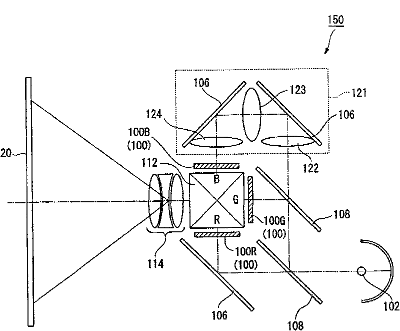
[0099] like Figure 1B As shown, a projection optical system 150 is ...
Embodiment approach 2
[0127] Below, refer to Figure 6 Embodiment 2 of the present invention will be described. Figure 6 is a schematic configuration diagram of the screen main body in this embodiment, Figure 7A , 7B is an exploded view of the main body of the screen.
[0128] like Figure 6 As shown, the screen main body 40 is configured to give flow in a direction perpendicular to the flow direction of the diffuser 34 flowing in the flow path 41 . like Figure 6 ~ 7B As shown, a plurality of wall portions 42 (third partition walls) perpendicular to the partition walls 27 and wall portions 43 (third partition walls) perpendicular to the partition walls 28 are provided. The wall portions 42, 43 extend vertically in the left-right direction (x direction) from the front and back surfaces of each partition wall 27, 28, and have a length that never touches the opposing partition wall 27, 28, that is, has a length longer than that of the adjacent partition wall 27, 28. 28 intervals between short...
Embodiment approach 3
[0133] Below, refer to Figure 8 ~ 9B Embodiment 3 of the present invention will be described. Figure 8 is the cross-sectional view of the screen body in the focus direction (z direction), Figure 9A , 9B is an exploded view of the main body of the screen.
[0134] The screen main body 40 in the above-mentioned embodiment is a screen main body in which the diffuser 34 flows in the left and right directions while reciprocating in the vertical direction of the screen main body 40 , but the configuration of the screen main body 50 in the present embodiment is as follows: Figure 8 As shown, the scatterers 34 flow toward the left-right direction (x-direction) of the screen main body 50 while reciprocating in the focusing direction (z-direction) between the opposing light-transmitting plates 23 .
[0135] like Figure 9A As shown, the partition walls 51 and 52 of the present embodiment have the same length, and the length in the longitudinal direction corresponds to the length...
PUM
 Abstract
Description
Claims
Application Information