Door hinge with concealed bearing

A hinge device and hidden technology, applied in door/window fittings, wing parts, hinges, etc., can solve problems such as heavy rotation, high wear, and obstruction to door rotation

Active Publication Date: 2008-01-09
ECO SCHULTE
View PDF6 Cites 0 Cited by
  • Summary
  • Abstract
  • Description
  • Claims
  • Application Information

AI Technical Summary

Problems solved by technology

Theoretically speaking, the door hinges in the prior art are equipped with bearing components, and it is hoped that the bearing components will bear the radial friction force of the door shaft, but due to the unreasonable structure of the internal and external door hinge units, when the internal door hinge unit When rotating, other parts other than the bearing parts also bear the radial friction of the door shaft, which hinders the door from rotating.
When the various parts of the hinge device are installed with deviations, or when they are used for a long time, the phenomenon that the bearing parts are not stressed and the claw parts are stressed, the hinge device is severely worn, the rotation is heavy, and the service life is short. For heavy doors , the hinge device needs to be replaced frequently, which brings inconvenience to people
[0003] German patent DE-OS 24 12 725 introduces this type of door hinge. The door hinge disclosed in this patent has the following disadvantages: since the rotating parts and bearing grooves are made of the same material, in the above-mentioned patents all use In addition, the bearing groove adopts a conical shape, and when the rotating element is spherical, there is only a narrow annular contact surface between the rotating element and the bearing groove, which It will also lead to high wear of the bearing device
The hinge mechanism is also subject to severe wear and heavy turning

Method used


Image

  • Door hinge with concealed bearing
  • Door hinge with concealed bearing
  • Door hinge with concealed bearing

Examples


Embodiment Construction

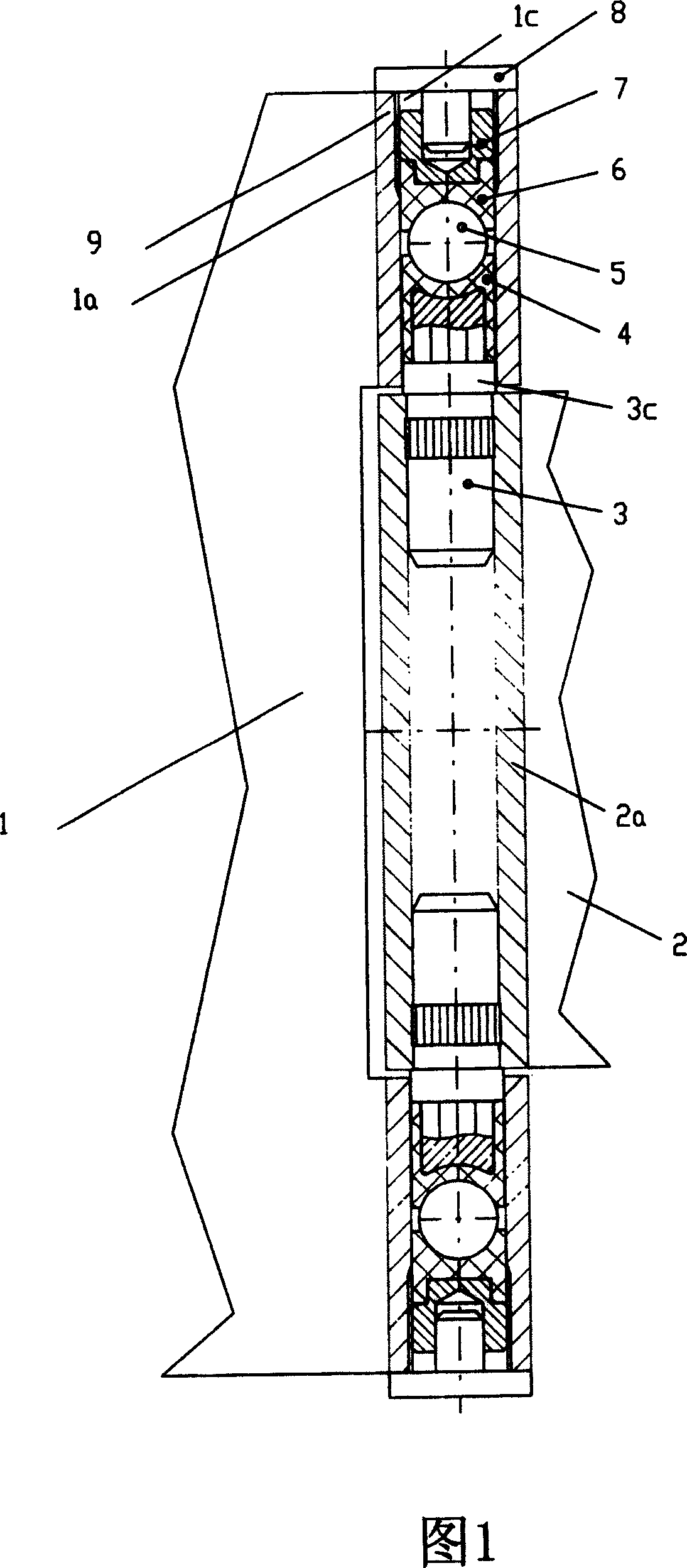
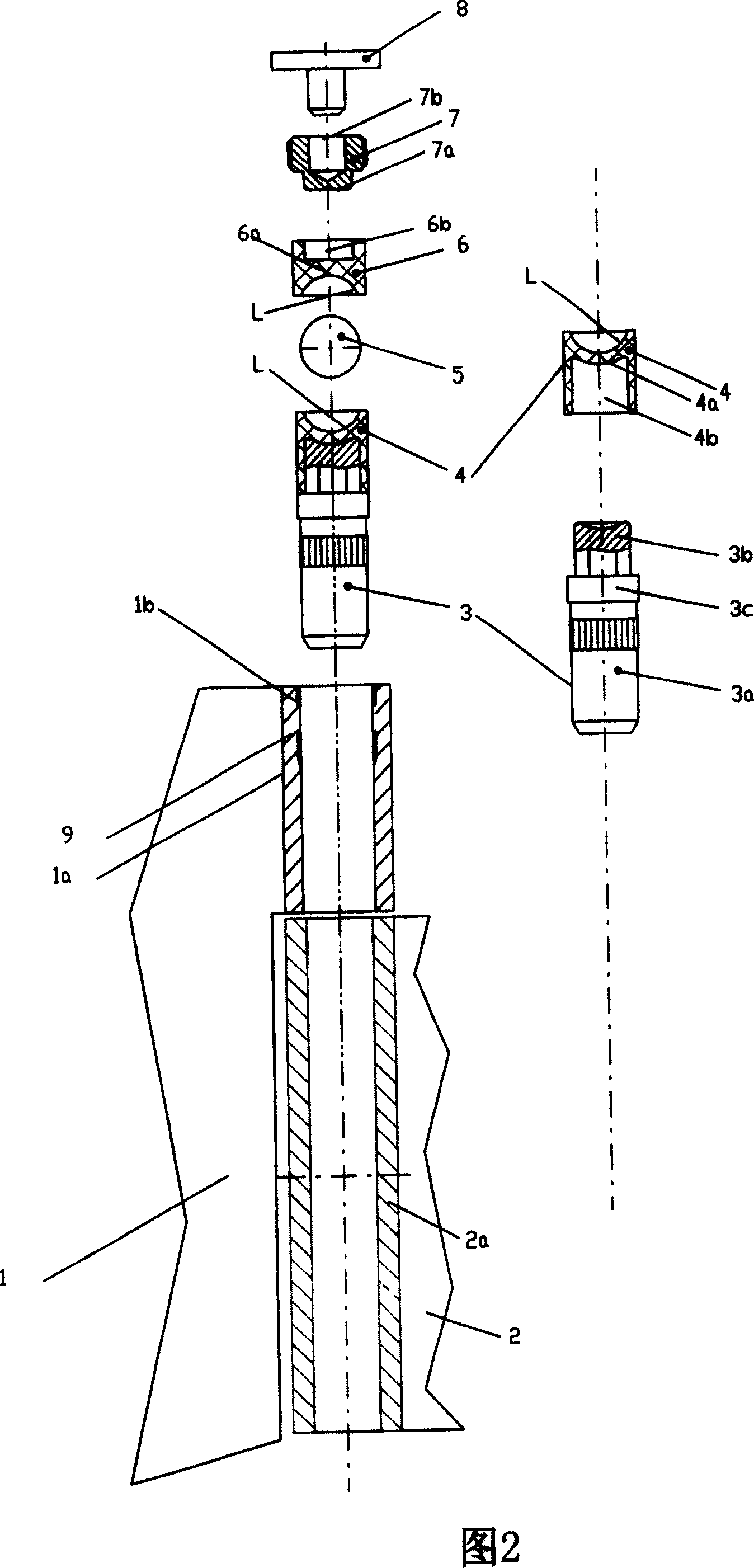
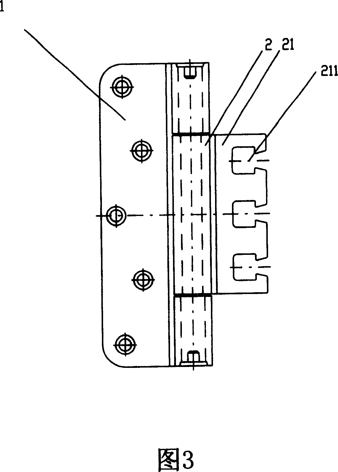
[0012] A door hinge device consisting of an inner and outer door hinge unit including additional means to allow it to be mounted to a door frame or door; the inner door hinge unit is mounted on the Between two or more cylindrical bearing parts on the external door hinge unit; inside the bearing parts there are first bearing sleeve and second bearing sleeve are set, the bearing sleeve is made of special engineering material plastic steel POM PTFE It is made; there is a ball between the first bearing sleeve and the second bearing sleeve, the ball is made of metal material, the door hinge device also includes a supporting bolt and an adjusting screw, and the first bearing sleeve is close to the inner The direction of the door hinge unit is firmly sleeved on the free end of the support bolt; the adjustment screw can be screwed into the bearing part; the second bearing sleeve is subjected to the counter pressure of the ball, away from the first bearing sleeve.

[0013] The door hin...


PUM


Abstract

The plate has outer and inner parts (1, 2) with a fastening unit for mounting the plate on a door frame. The inner part is placed between two cylindrical supporting sections (1a), which are placed on the outer part. Two supporting parts (4, 6) made up of rugged plastic such as Teflon, are placed between the sections. A ball (5) made of steel is arranged between the parts (4, 6), and a set screw (7) is screwed into the sections. - The support part (6) exerts pressure against the ball (5) using the set screw, where the ball exerts the pressure against the support part (4).

Description

technical field [0001] The invention relates to a hinge device for a door, in particular to a hinge for a door which is easy to rotate, wears very little, does not need maintenance and can adjust its installation position three-dimensionally. Background technique [0002] Existing door hinges generally consist of an inner and an outer door hinge unit which include additional means to allow it to be mounted to the door frame or door. The inner door hinge unit is installed between two or more cylindrical bearing parts on the outer door hinge unit, and the bearing parts are exposed to the outside. Theoretically speaking, the door hinges in the prior art are equipped with bearing components, and it is hoped that the bearing components will bear the radial friction force of the door shaft, but due to the unreasonable structure of the internal and external door hinge units, when the internal door hinge unit When rotating, other components other than the bearing components also be...

Claims


Application Information

Patent Timeline
Patent Type & Authority Patents(China)
IPC IPC(8): E05D5/14E05D7/04E05D11/04
CPCE05D2011/045E05D11/04E05Y2900/132
Inventor 本哈德·邓施罗尔
Owner ECO SCHULTE
Why Eureka
Try Eureka