Omnidirectional image reflector

An omnidirectional image and mirror technology, applied in mirrors and other directions, can solve the problems of single viewpoint, low cost, distortion and other problems of the image, and achieve the effect of solving visual blind spots

Inactive Publication Date: 2008-01-09
YANSHAN UNIV
View PDF4 Cites 0 Cited by
  • Summary
  • Abstract
  • Description
  • Claims
  • Application Information

AI Technical Summary

Problems solved by technology

[0006] In order to solve the problems in the above-mentioned imaging mirrors, the present invention provides an omnidirectional image mirror, which can easily solve the problems in the above-mentioned imaging mirrors with high imaging performance and low cost, that is, to obtain Single Viewpoint Constraint Problem of Image and Distortion Problem of Mapped Perspective Projection Image

Method used


Image

  • Omnidirectional image reflector
  • Omnidirectional image reflector
  • Omnidirectional image reflector

Examples


Embodiment Construction

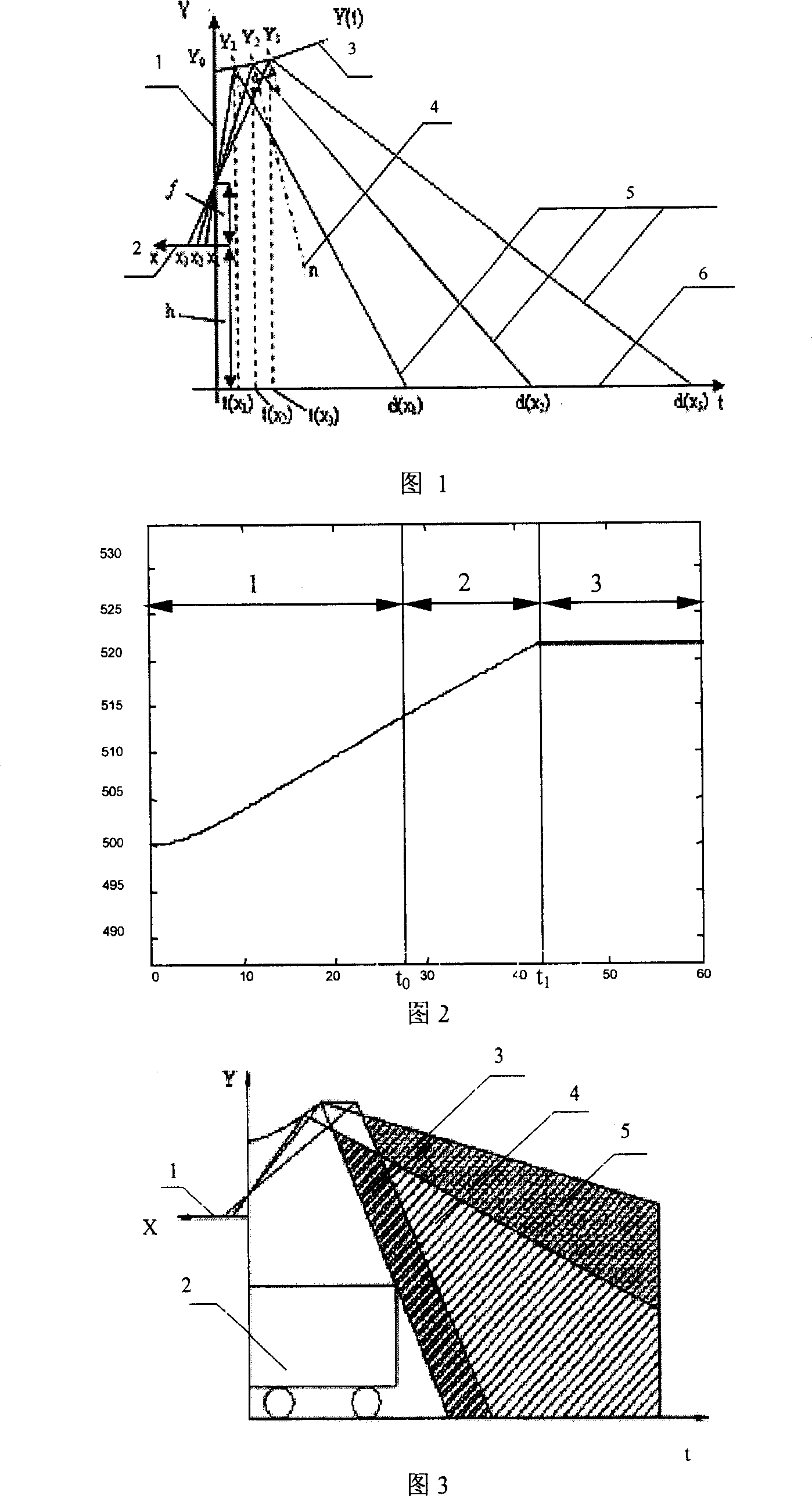
[0030] The following takes a specific omnidirectional image mirror as an example to illustrate the manufacturing process of the omnidirectional image mirror: the size of the mirror is: the radius of the mirror is 60 cm, and the total height is 25 cm. The range height of the test target object is 85cm, the range of the test target object of the undistorted image is an area with the optical axis as the center radius of 3200cm, and the test range of the total target object is the area with the optical axis as the center radius of 9300cm.

[0031] The equation of the first part of the geometric mirror is: Y ′ = - n ± m 2 + n 2 m

[0032] exist Y ′ = ...


PUM


Abstract

The omnidirectional image reflector is one kind of image reflector with relatively small mirror but relatively large view field and capable of obtaining no-deformation near distance image. The omnidirectional image reflector utilizes the planar mirror in the edge to form whole field mapped image without blind area. The reflector has cross sections perpendicular to the axis as concentric circles, axis-passing sections comprising isometric parallel, equi-slope straight line and zero-slope horizontal straight line, no-inflection point connection between the isometric mapping section curve and the equi-slope section curve, and smooth connection between the equi-slope section curve and the planar section straight line. The omnidirectional image reflector features no deformation, great visual field, no blind point, etc. and is used mainly in robot visual navigation, video meeting, monitoring and scene recovering.

Description

technical field [0001] The invention relates to a new type of omnidirectional image mirror, which is mainly used in the fields of robot visual navigation, video conferencing, monitoring, monitoring and scene restoration, especially in the visual navigation of mobile robots, which can quickly Accurate tracking and positioning of target objects. Background technique [0002] According to the imaging principle, the methods for obtaining omnidirectional information images are roughly divided into the following three types: rotating imaging or multi-camera imaging; fisheye lens imaging or standard curved surface omnidirectional mirror imaging. [0003] Rotational imaging is to use an ordinary camera to rotate around a vertical axis passing through its optical center, obtain multiple images of different angles during the rotation, and splicing or re-sampling these images to obtain omnidirectional image information. Since the physical position of the optical center of the camera c...

Claims


Application Information

Patent Timeline
Patent Type & Authority Patents(China)
IPC IPC(8): G02B5/09G02B5/10G02B5/08
Inventor 王志松曾达幸王春雷
Owner YANSHAN UNIV
Why Eureka
Try Eureka