Supercharge Your Innovation With Domain-Expert AI Agents!

Vortex type compressor

A technology of scroll compressors and compression chambers, applied in the direction of rotary piston machines, rotary piston pumps, mechanical equipment, etc., can solve the problems of reducing compressor efficiency, increasing sliding loss, increasing leakage loss, etc., to achieve The effect of reducing losses

Inactive Publication Date: 2008-01-16
HITACHI JOHNSON CONTROLS AIR CONDITIONING INC
View PDF7 Cites 0 Cited by
  • Summary
  • Abstract
  • Description
  • Claims
  • Application Information

AI Technical Summary

Problems solved by technology

As a result, the sliding loss increases when the back pressure is too large, and the leakage loss increases when the back pressure is too small, so there is a problem that the efficiency of the compressor is lowered anyway.

Method used


Image

  • Vortex type compressor
  • Vortex type compressor
  • Vortex type compressor

Examples


Embodiment Construction

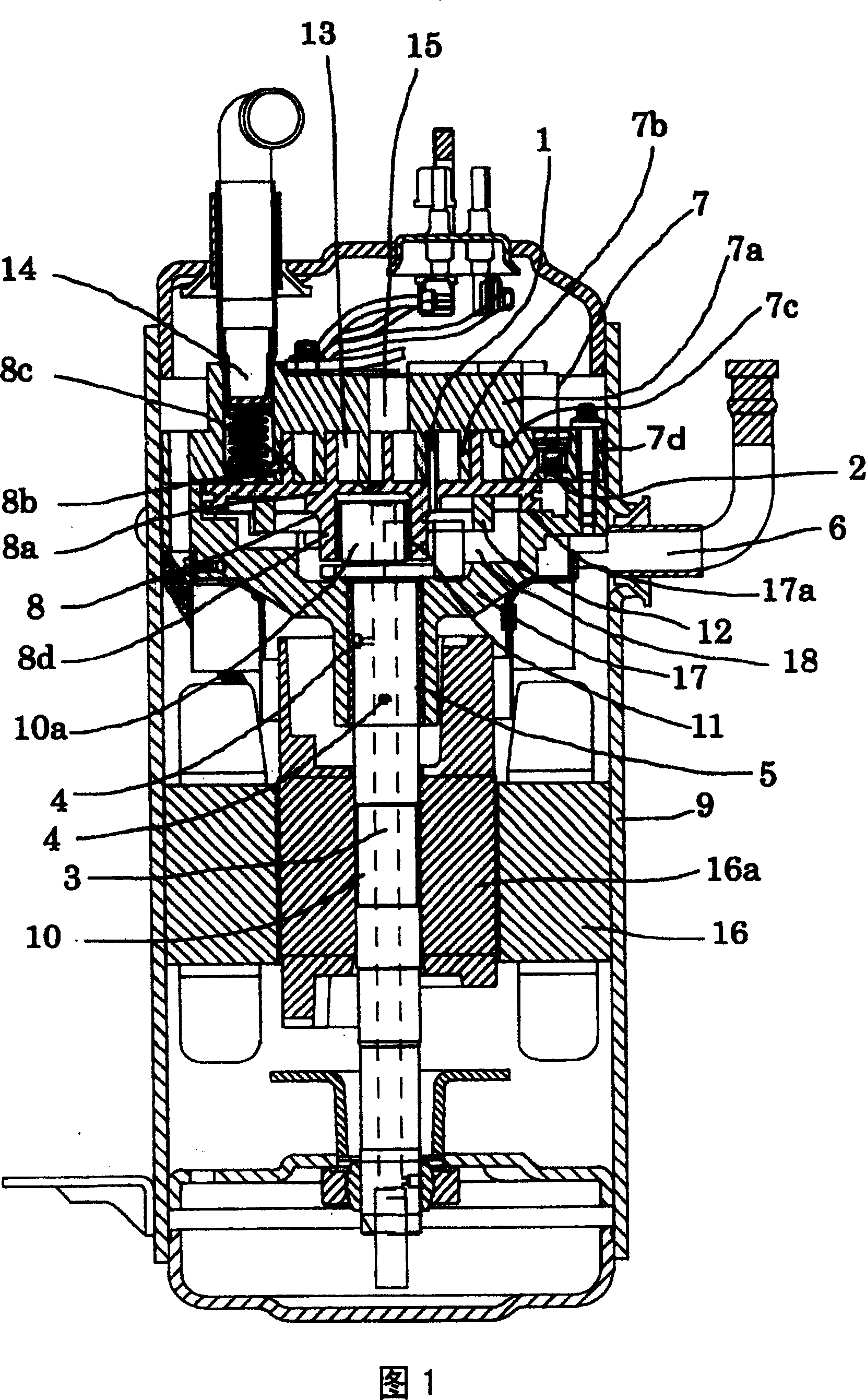
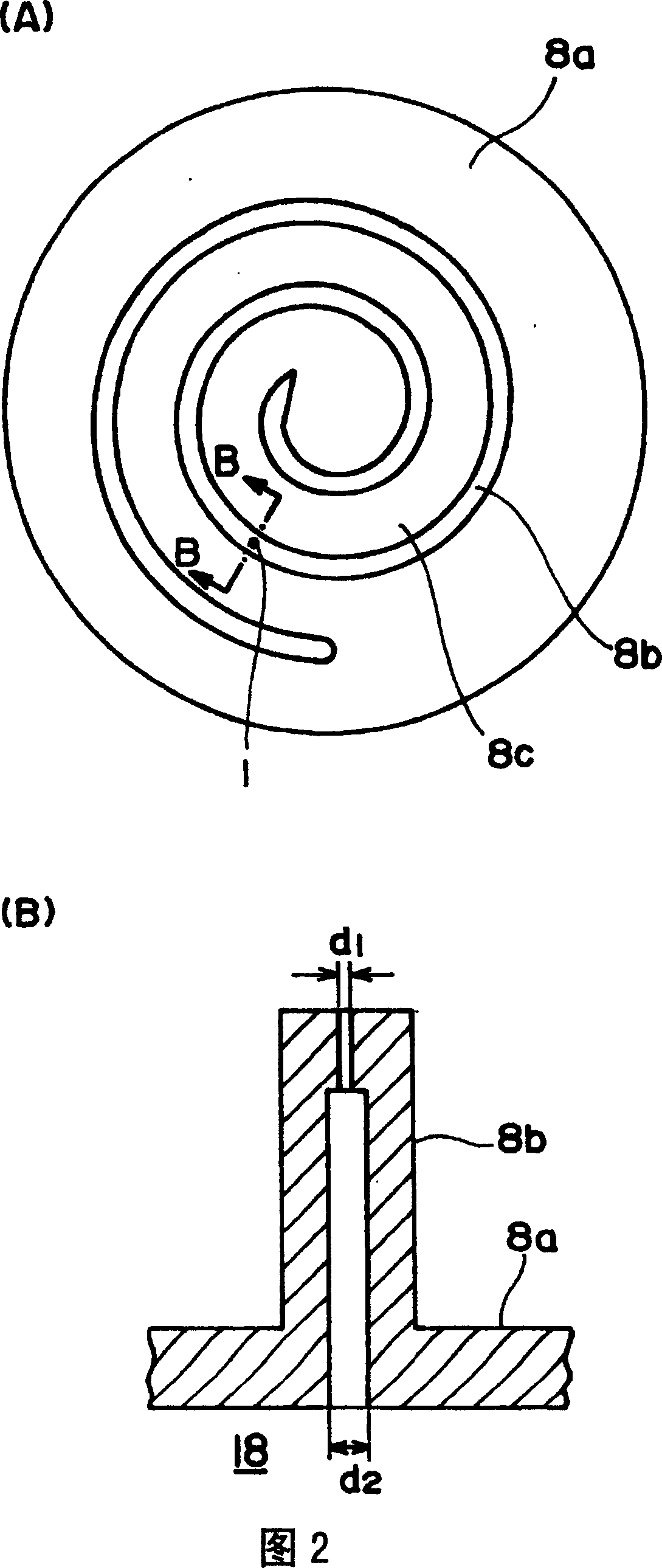
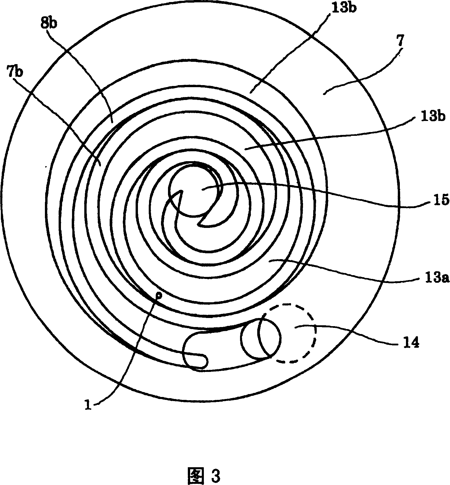
[0021] Hereinafter, an embodiment of the present invention will be described with reference to the drawings. Fig. 1 is an overall longitudinal sectional view of a scroll compressor according to an embodiment of the present invention. Fig. 2(A) is a plan view of the movable scroll seen from the lap side of the characteristic part of this embodiment, and (B) is a B-B cross-sectional view of Fig. 1(A).

[0022] As shown in FIG. 1 , the fixed scroll 7 is composed of a disk-shaped end plate 7 a, a spiral coil 7 b erected on the end plate 7 a, and a spiral coil 7 b positioned on the outer peripheral side of the end plate 7 a and formed to surround the coil. 7b is constituted by a cylindrical support portion 7d. The surface of the end plate 7a on which the coil plate 7b is erected is the tooth bottom 7c. In addition, the fixed scroll 7 is fixed to the frame 17 with bolts or the like at the support portion 7d, and the frame 17 integrated with the fixed scroll 7 is fixed to the casin...


PUM


Abstract

A scroll compressor is provided with: a back-pressure chamber 18 which is provided on the back side of the rotating scroll 8 rotatably provided opposite the stationary scroll 7 and which an intermediate pressure between a discharge pressure and a suction pressure is introduced into; a back-pressure adjustment valve 2 which releases fluid in the back-pressure chamber into a suction chamber or a compression chamber in an initial stage of compression through a communication passage 2f formed at an addendum of the outermost circumference lap 7e of the stationary scroll, according to a difference between a suction pressure introduced through the communication passage 2f or a compression initial pressure and a pressure in the back-pressure chamber. The rotating scroll 8 is provided with a through hole 1 which communicates a compression chamber 13 uncommunicated with the communication passage 2f, with the back-pressure chamber 18, and the compression loss due to reexpansion is reduced by releasing part of an excessive pressure of the back-pressure chamber 18 into the compression chamber 13. So the loss which due to a back-pressure adjustment to adjust an attracting force between a stationary scroll and a rotating one can reduce.

Description

technical field [0001] The present invention relates to scroll compressors. Background technique [0002] Scroll compressors, the fixed scroll and the movable scroll with the spiral coils installed upright on the end plate are arranged face to face and the coils are meshed, so that the movable scroll rotates and is formed on the coils successively. The volume of the multiple compression chambers in between, thereby compressing the fluid. This compression action generates an axial force (hereinafter, referred to as disengagement force) that separates the fixed scroll and the movable scroll from each other. If the two scrolls are separated, there will be a gap between the tip of the coil plate and the end plate, which will damage the sealing of the compression chamber and reduce the efficiency of the compressor. For this reason, a back pressure chamber is formed on the back of the end plate of the movable scroll, and the intermediate pressure between the compressor discharge...

Claims


Application Information

Patent Timeline
Patent Type & Authority Patents(China)
IPC IPC(8): F04C18/02
CPCF04C18/0215F04C18/0246F04C29/0021F04C29/124F04C2210/26F04C2240/40Y10S415/00Y10S417/00
Inventor 近野雅嗣大岛健一岸康弘岛田昌浩佐藤英治
Owner HITACHI JOHNSON CONTROLS AIR CONDITIONING INC
Features
  • R&D
  • Intellectual Property
  • Life Sciences
  • Materials
  • Tech Scout
  • Unparalleled Data Quality
  • Higher Quality Content
  • 60% Fewer Hallucinations
Learn More