Shaft seal method of screw rotor automatic seal of impeller pump

A self-sealing, impeller-type technology, applied to non-variable pumps, components of pumping devices for elastic fluids, pumps, etc., can solve problems such as failure of dynamic sealing, complex manufacturing process, and various structural designs. To achieve the effect of compact sealing structure, reducing consumption cost and widening the application range

Inactive Publication Date: 2008-01-23
贺友林
View PDF4 Cites 0 Cited by
  • Summary
  • Abstract
  • Description
  • Claims
  • Application Information

AI Technical Summary

Problems solved by technology

[0003] 1. Packing seal: Although the structure is simple, cheap and easy to maintain, it is easily damaged, has a short service life, large leakage, large energy consumption and low efficiency
[0004] 2. Mechanical seal: Mechanical seal is also called end face seal. Although it has better sealing effect, less leakage and longer service life, it has many structural designs, complex manufacturing process, high material requirements and expensive consumables. In some occasions, it is necessary to flush and replace the seals with cleaning solution
[0005] 3. Power seal: The power seal is divided into two types: the back blade and the auxiliary impeller. When the impeller pump is working normally, the centrifugal force of the back blade or the auxiliary impeller makes the shaft seal in a state of normal pressure or negative pressure, so the pump is working normally. However, when the impeller pump stops working and the centrifugal force disappears, the dynamic sealing effect of the back blade or auxiliary impeller will also fail accordingly. At this time, it has to be sealed by the parking sealing device made of packing. That is, the packing seal commonly used at present also has the disadvantages in the above 1; although the dynamic seal has reliable sealing performance, convenient maintenance and low price when the pump is working, there is still leakage when the pump is stopped

Method used


Image

  • Shaft seal method of screw rotor automatic seal of impeller pump

Examples


Embodiment Construction

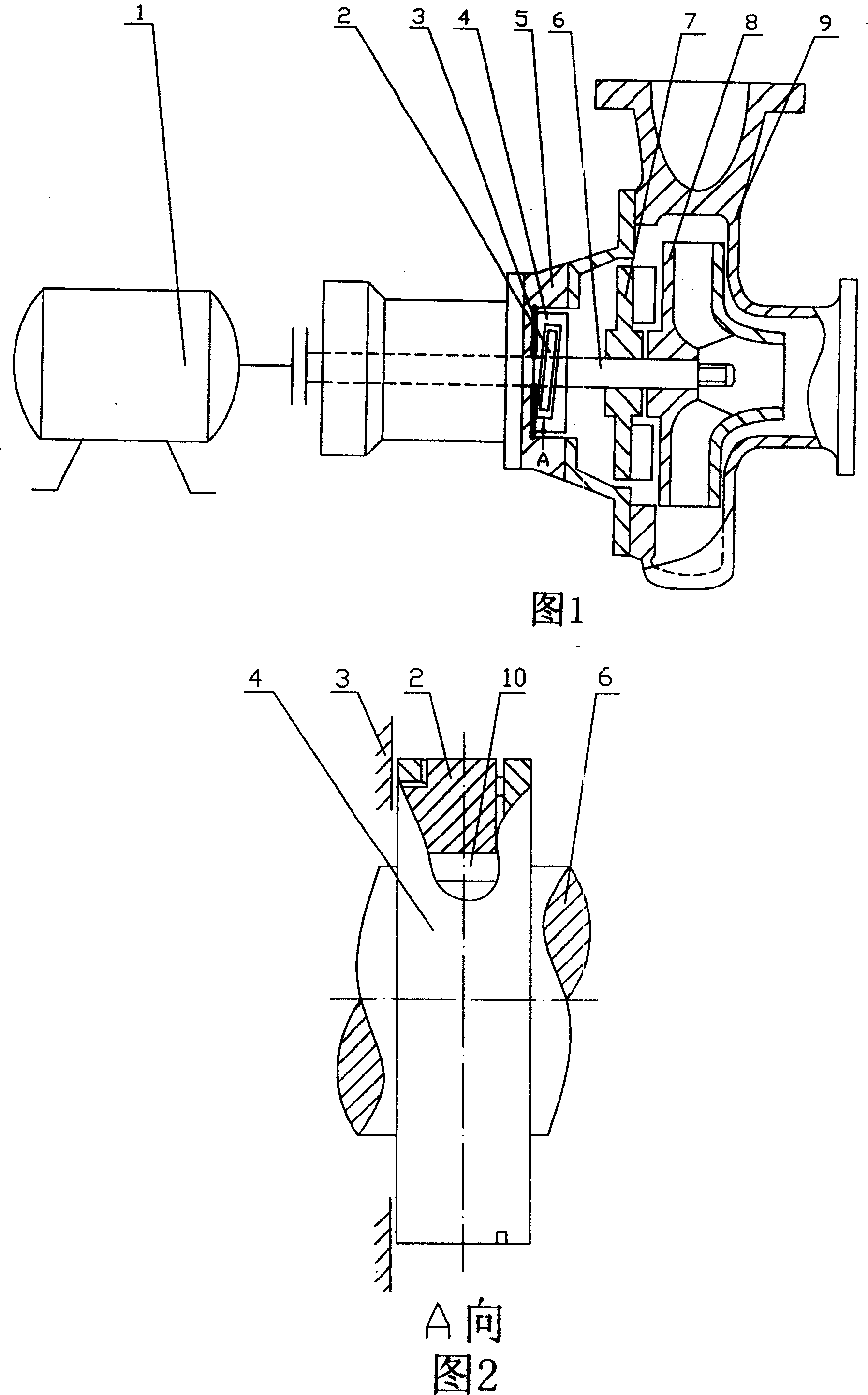
[0017] Shown in Fig. 1, 2 is one of embodiment of the present invention, is the impeller type centrifugal pump of application single suction port of the present invention, the impeller type centrifugal pump of the single suction port of a helical rotor automatic sealing device is housed on the pump shaft 6, comprises The impeller centrifugal pump composed of pump body 9, pump cover 5, pump shaft 6, main and auxiliary impellers 8 and 7 made of corrosion-resistant alloy steel, and motor 1 is characterized in that it is connected with the shaft sealing point in the impeller centrifugal pump 9 body Corresponding to the sealing end face 3, the screw rotor automatic sealing device composed of the active and driven screw rotors 2, 4 and key 10 made of corrosion-resistant alloy steel is installed on the 6th section of the pump shaft. Corroded rubber sealing layer, the automatic sealing device can rely on the generated inertia force during the whole process of centrifugal pump operation...


PUM


Abstract

The invention relates to a shaft sealing method for automatically sealing spiral rotor of a vane pump, characterized in that corresponding to shaft sealing point, a pump shaft segment is installed with an automatic sealing device composed of driving and driven spiral rotors, in the pump operating course, depending on the generated inertia force, under the action of the driving spiral rotor, following the driving and driven to generate radial relative angle displacement and simultaneously making axial two-way displacement so as to separate from and combine with pump body shaft sealing point, and in the place of the sealing end surface, implementing no fixed end surface contact as the pump operating and automatic sealing as stopping. It is novel and special, reliable to operate, safe and convenient to use, energy-saving, low-cost, and wide-application range.

Description

technical field [0001] The invention relates to a sealing method for an inner shaft seal of an impeller pump, in particular to an automatic sealing shaft seal for a helical rotor of an impeller pump which can ensure the dynamic seal of the impeller pump and realize the leak-free sealing when the impeller pump stops. method. Background technique [0002] At present, as a mechanical pump for liquid medium transportation and pressurization, it is widely used in various production fields, among which impeller pumps are mostly, and impeller pumps include: centrifugal pumps, vortex pumps, mixed flow pumps, axial flow pumps, etc. Among them, the impeller centrifugal pump is the most widely used in the chemical industry, reaching more than 80%. Impeller pumps are divided into single-suction type and double-suction type according to the distribution of suction ports. They are composed of pump body, pump cover, pump shaft, main and auxiliary impellers, shaft seals and motors. In the ...

Claims


Application Information

Patent Timeline
Patent Type & Authority Patents(China)
IPC IPC(8): F04D29/14F04D29/10
Inventor 贺友林
Owner 贺友林
Why Eureka
Try Eureka