Equipment used for space position precise measurement

A technology for precise measurement and spatial position, which is applied in the application field of laser photoelectric measurement technology to achieve the effect of solving real-time measurement and achieving high-precision measurement requirements

Active Publication Date: 2008-01-23
NUCTECH CO LTD +1
View PDF2 Cites 1 Cited by
  • Summary
  • Abstract
  • Description
  • Claims
  • Application Information

AI Technical Summary

Problems solved by technology

But for the other four position information, that is, the angle between the two planes of the object (the degree of freedom of the rotation of the two axes in the plane) and the position of the two calibration points (the degree of freedom of the two calibration points in the plane relative to the origin of the coordinates), there is no good information at present. Even if expensive high-precision measurement and calibration instruments are used, it can only solve the initial installation problem and cannot realize real-time spatial position measurement and calibration

Method used


Image

  • Equipment used for space position precise measurement

Examples


Embodiment Construction

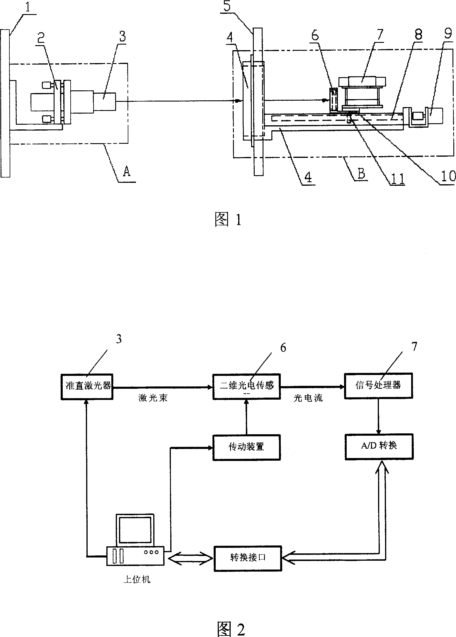
[0012] Referring to Fig. 1, the present invention comprises emission reference plate 1, collimating laser 3, beam adjuster 2, receiving reference plate 5, support frame 4, adopts two-dimensional photoelectric sensor 6 and signal processor 7 of two-dimensional PSD or two-dimensional CCD . The collimated laser 3 is connected with the beam adjuster 2, and the beam adjuster 2 is installed on the emission reference plate 1 to make the laser beam coincide with the normal line of the emission reference plate 1 to form a laser emitting device A. The receiving reference plate 5 is fixed to the side end of the support frame 4, and the transmission device is installed on the support frame 4. A two-dimensional photoelectric sensor 6 and a signal processor 7 are installed on the transmission device, and the moving track of the coordinate center of the detection surface of the two-dimensional photoelectric sensor 6 is consistent with the normal line of the receiving reference plate 5 to for...


PUM


Abstract

A kind of equipment used to measure the space location precisely belongs to the application field of the laser photoelectricity measure technique. The invention includes an emission base board, a collimation laser device, a beam regulator, a receiving base board, a supporting bracket, a two-dimension photoelectricity sensor and a signal treating device. The collimation laser device and the beam regulator are connected. The beam regulator is installed on the emission base board and makes the laser beam consistent with the normal of the emission base board to form the laser emission device. The receiving base board is connected with the side end of the supporting bracket. On the supporting bracket installs the gearing, on which installs the two-dimension photoelectricity sensor and the signal treating device. The coordinate center motion locus of the two-dimension photoelectricity sensor detecting surface is consistent with the normal of the receiving base board to form the photoelectricity detecting device. The invention uses the space location measure system of laser photoelectricity and four freedoms to realize the precise measure of the space location relation between the remote objects.

Description

technical field [0001] The invention relates to a device for realizing precise measurement of long-distance spatial positions by utilizing the principle of laser photoelectric measurement, and belongs to the application field of laser photoelectric measurement technology. Background technique [0002] In the fields of astronomy, aerospace, military and electromechanical engineering, some precision equipment needs to be positioned remotely and perform real-time spatial position measurement and calibration, which requires the establishment of two remotely calibrated spatial coordinate systems. In the prior art, for the two coordinate systems, there are six degrees of freedom between each other, that is, the three position information of X, Y, and Z formed by the line connecting the two coordinate origins and the plane perpendicular to the line passing through two points And the angle information of the rotation around the connection line can be realized by using laser distance...

Claims


Application Information

Patent Timeline
Patent Type & Authority Patents(China)
IPC IPC(8): G01B21/04G01B11/03
Inventor 吴万龙高文焕李元景金永杰胡晓伟
Owner NUCTECH CO LTD
Why Eureka
Try Eureka