Coaxial connector
A coaxial connector and connector technology, applied in the direction of connection, two-part connection device, electrical components, etc., can solve the problems of weak locking force, weak cylindrical part strength, and plug falling off, and achieve the effect of good high frequency performance.
- Summary
- Abstract
- Description
- Claims
- Application Information
AI Technical Summary
Problems solved by technology
Method used
Image
Examples
no. 1 approach
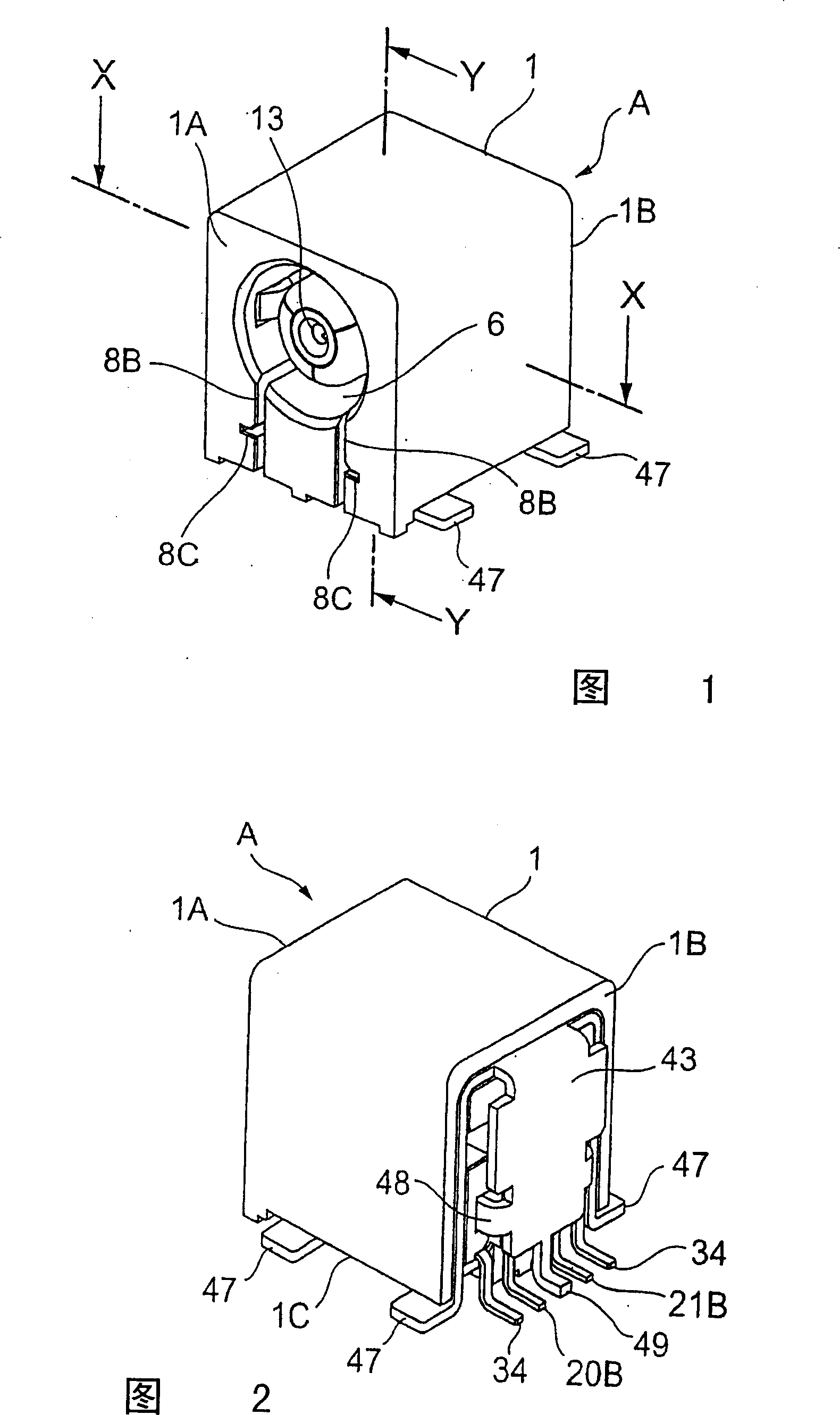
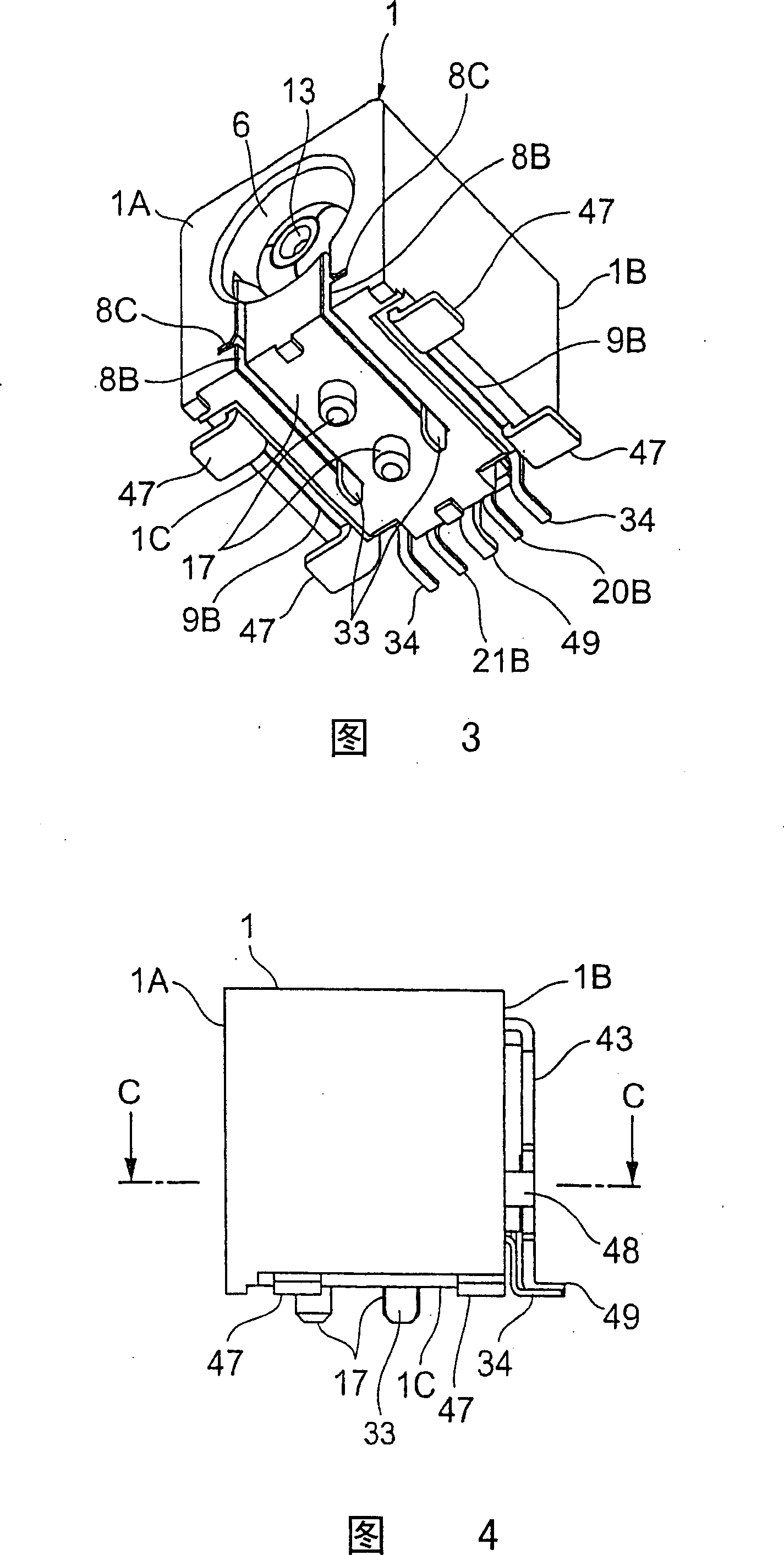
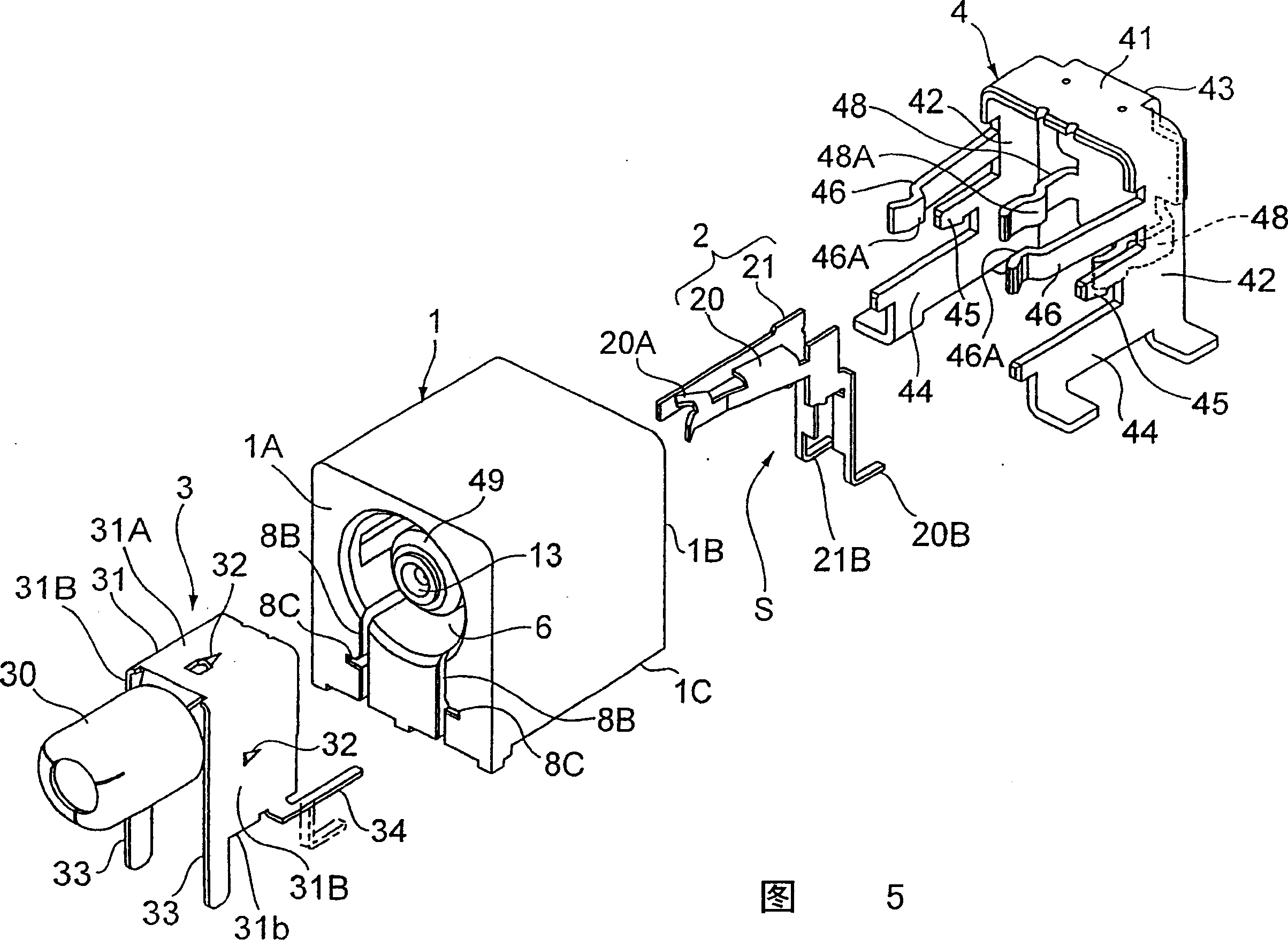
[0081] 1 to 15 show the first embodiment of the coaxial connector of the present invention.
[0082] 1 is a perspective view of a coaxial connector of the present invention, that is, a socket (first embodiment) as viewed from the front, FIG. 2 is a perspective view of the socket as viewed from the rear, and FIG. 3 is a view from the bottom of the socket. 4 is a side view of the socket, FIG. 5 is a perspective view of an exploded state viewed from the front of the socket, and FIG. 6 is a perspective view of an exploded state viewed from the back of the socket.
[0083] The receptacle A which is the coaxial connector of the present invention is used for coupling with the plug B which is the counterpart connector. As shown in FIG. 5, the socket A is composed of an insulating case 1, an inner conductor 2, and first and second outer conductors 3 and 4 constituting outer conductors.
[0084] On the insulating case 1, as shown in FIGS. The inner conductor mounting part 7 is formed ...
Embodiment approach
[0113] According to the above-mentioned first embodiment of the present invention, the outer conductor is composed of the first outer conductor 3 and the second outer conductor 4, and the first and second outer conductors 3 and 4 are respectively assembled in the insulating case 1, so that the second outer conductor The contact portion 48 of the conductor 4 is in contact with the first outer conductor 3, thereby making it electrically conductive to each other, so it is easy to assemble, and the back side 43 covers the back side of the switch terminal 20 and the connection terminal 21, and also connects the back side board part, that is, the lead part 49 is located between the lead parts 20B and 21B of the switch terminal 20 and the connection terminal 21, so that the switch terminal 20 and the connection terminal 21 can be completely shielded and good high-frequency performance can be obtained. In addition, by engaging the engaging portion 46A of the locking piece portion 46 of...
no. 2 approach
[0121] 16 to 23 are the second embodiment of the coaxial connector of the present invention. Components having the same configuration as those of the above-mentioned first embodiment of the present invention are denoted by the same reference numerals and description thereof will be omitted.
[0122] In the second embodiment of the present invention, the pair of contact portions 48 of the back shield portion 43 of the second outer conductor 4 are brought into contact with the side shield portion (side surface portion of the first outer conductor 3 ) 31B of the first outer conductor 3 , and the second The end shield portion 31A of an outer conductor 3 contacts the back shield portion 43 via the conductor contact mechanism F to constitute a contact mechanism for making the first outer conductor 3 contact the second outer conductor 4,
[0123] That is, as shown in FIG. 16 and FIG. 17 , a portion of the facing end portion of the first outer conductor 3 facing the second outer condu...
PUM
 Abstract
Description
Claims
Application Information
 - R&D
- Intellectual Property
- Life Sciences
- Materials
- Tech Scout
- Unparalleled Data Quality
- Higher Quality Content
- 60% Fewer Hallucinations
Browse by: Latest US Patents, China's latest patents, Technical Efficacy Thesaurus, Application Domain, Technology Topic, Popular Technical Reports.
© 2025 PatSnap. All rights reserved.Legal|Privacy policy|Modern Slavery Act Transparency Statement|Sitemap|About US| Contact US: help@patsnap.com


