Cuttings recovering apparatus for electrode trimmer

A recovery device and electrode head technology, applied in the direction of electrode characteristics, resistance welding equipment, maintenance and safety accessories, etc., can solve the problems of difficult chip recovery and large-scale equipment

Inactive Publication Date: 2008-03-12
小原(南京)机电有限公司
View PDF5 Cites 0 Cited by
  • Summary
  • Abstract
  • Description
  • Claims
  • Application Information

AI Technical Summary

Problems solved by technology

[0005] However, in the prior art described above, since the compressed air is blown to one side of the cutter, the chips are drawn into the air, and the chips are flowed down to the other side of the cutter together with the air. It is difficult to recover the chips stuck around the electrode tip on the side
In addition, depending on the posture of the tip dresser, the chips flowing down to the other side of the cutter may float out of the shielding member, and the posture of the tip dresser must be restricted in order to collect the chips reliably.
Another problem is that making the chip catcher long will increase the size of the device

Method used


Image

  • Cuttings recovering apparatus for electrode trimmer
  • Cuttings recovering apparatus for electrode trimmer
  • Cuttings recovering apparatus for electrode trimmer

Examples


Embodiment Construction

[0015] Embodiments of the present invention will be described with reference to the drawings.

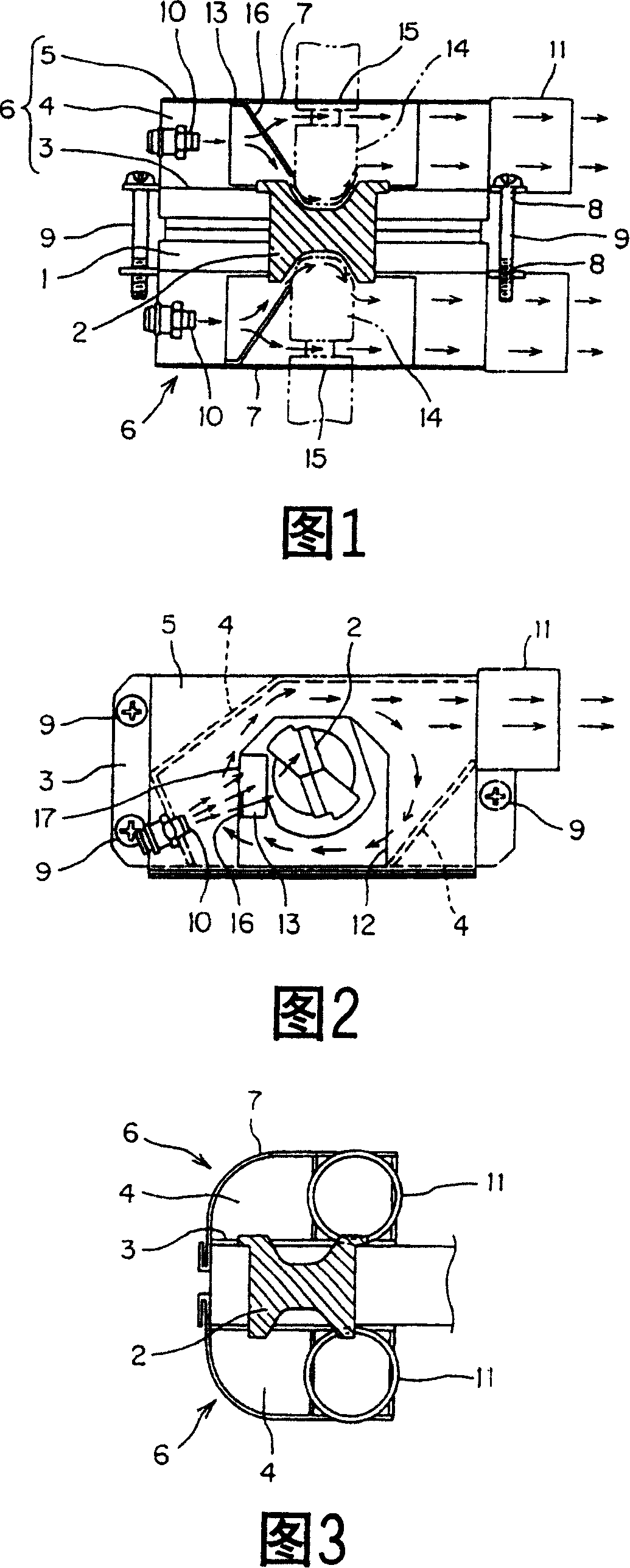
[0016] FIG. 1 is a front explanatory view of main parts of a tip dresser according to the present invention, FIG. 2 is a plan view thereof, and FIG. 3 is a side view thereof.

[0017] In the figure, 1 is a disc-shaped cutter frame, which holds a cutter 2 on the cutter frame 1, and a housing composed of a base plate 3, a side plate 4 and a partially opened cover plate 5 is arranged on both sides of the cutter 2 respectively. 6, 6. The opening surface of the casing 6 is covered by a cover 7 .

[0018] Screw holes 8, 8 .

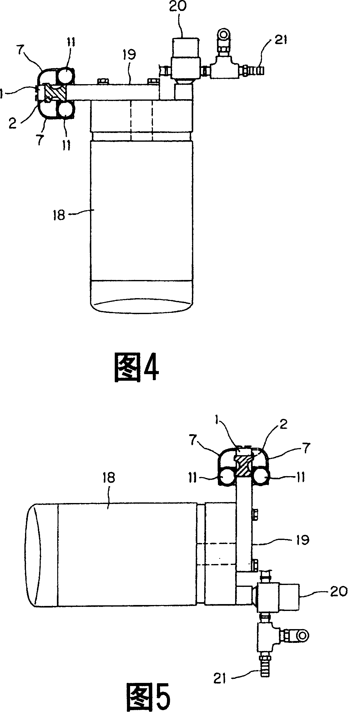
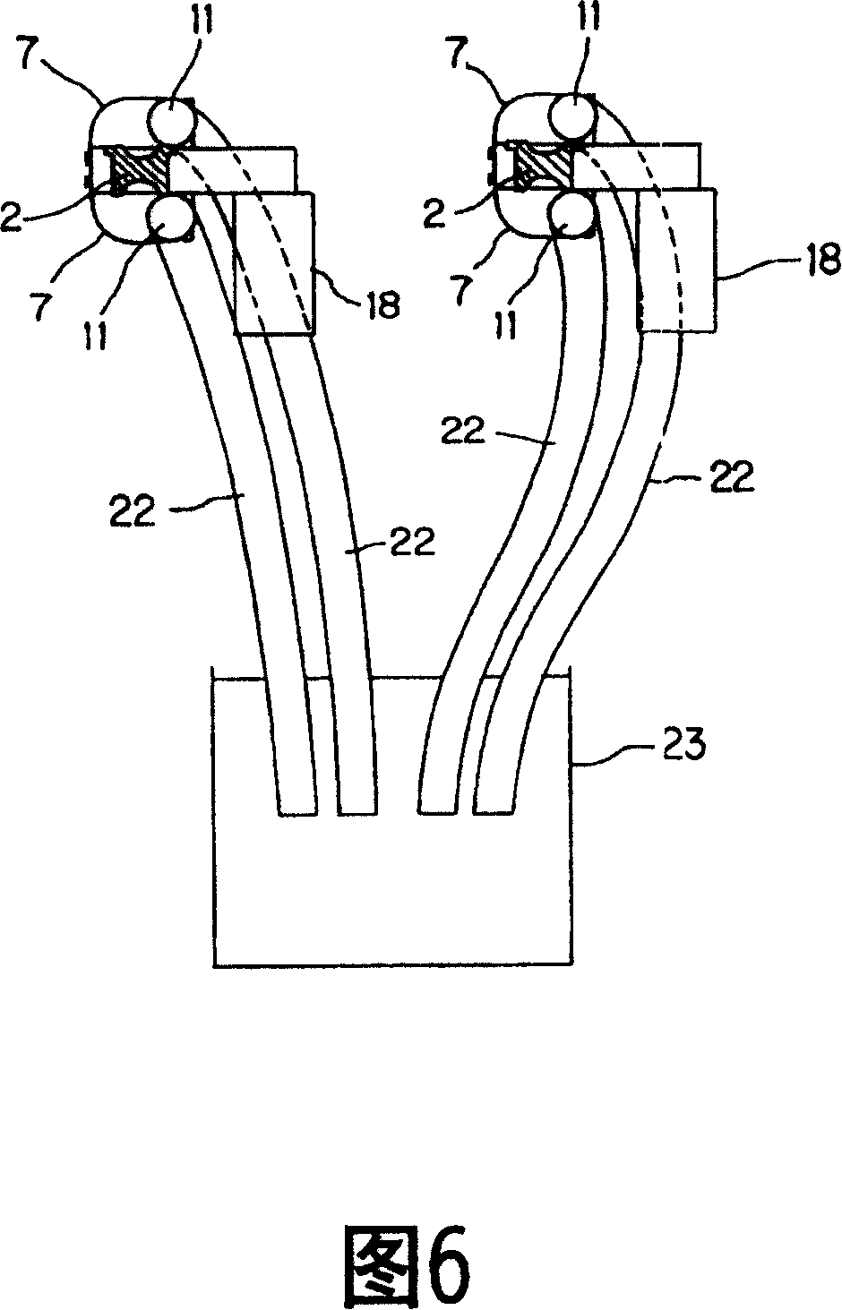
[0019] On the side plate 4 of the housing 6, a nozzle 10 for blowing compressed air is arranged, and a chip discharge port 11 is formed at a position opposite to the position where the nozzle 10 is arranged. In addition, the discharge port 11 may be arranged at an appropriate position in the casing 6 .

[0020] An opening 12 is formed in a part of the cover plate ...


PUM


Abstract

PURPOSE: A collecting device of cut powder is provided to certainly collect the cut powder by compacting the device. CONSTITUTION: Cases(6) are arranged in both ends of a cutter(2). The cases are covered by covers(7) having insertion holes(15) of electrode chips(14). Injection nozzles(10) of compressed air and outlets(11) of cutting dust are arranged in the cases respectively. Guide plates(16) are arranged between the nozzles and a cutter face to blow the compressed air to the cutter face and to generate the swirl inside the cases. Both cases are installed and removed by inserting both faces of the cutter between the cases and supporting. Thereby, the cut powder is collected certainly.

Description

technical field [0001] The present invention relates to a chip recovery device in an electrode tip dresser for recovering chips generated when dressing an electrode tip. Background technique [0002] Electrode tips used for spot welding, etc. are worn out due to repeated welding operations, and the electrode tips must be periodically trimmed to maintain welding quality. However, cutting chips are generated during dressing of the electrode tip. In order to recover the cutting chips, a known tip dresser blows compressed air into the cutter and recovers the cutting chips generated when the electrode tip is trimmed by grinding or grinding the tip. Specifically, a chip collection box with a flange shielding member arranged at the tip insertion port is installed at the lower part of the cutter, and compressed air is blown toward one side of the cutter, and the dust generated when the tip is trimmed is caught in the air. Chips flow down to the other side of the cutter together wit...

Claims


Application Information

Patent Timeline
Patent Type & Authority Patents(China)
IPC IPC(8): B23K11/30B23K11/36B23Q11/00
CPCB23Q11/005B23Q11/0064
Inventor 青木健太和泉武宏佐藤善宏
Owner 小原(南京)机电有限公司
Why Eureka
Try Eureka