Throttle device and fuel evaporative gas recovery system

A technology of throttling device and fuel evaporation, which is applied in charging system, combustion engine, low-pressure fuel injection, etc., can solve problems such as cost increase and parts increase, and achieve the effect of suppressing increase and reducing cost

Active Publication Date: 2020-06-30
MIKUNI CORP
View PDF35 Cites 1 Cited by
  • Summary
  • Abstract
  • Description
  • Claims
  • Application Information

AI Technical Summary

Problems solved by technology

[0005] However, in the above-mentioned metal tank arrangement structure or fuel evaporated gas recovery device, it is necessary to include an exhaust valve including a dedicated driving source. oversized, so not ideal

Method used


Image

  • Throttle device and fuel evaporative gas recovery system
  • Throttle device and fuel evaporative gas recovery system
  • Throttle device and fuel evaporative gas recovery system

Examples


Embodiment Construction

[0042] As follows, while referring to Figure 1 to Figure 11 , an embodiment of the present invention will be described.

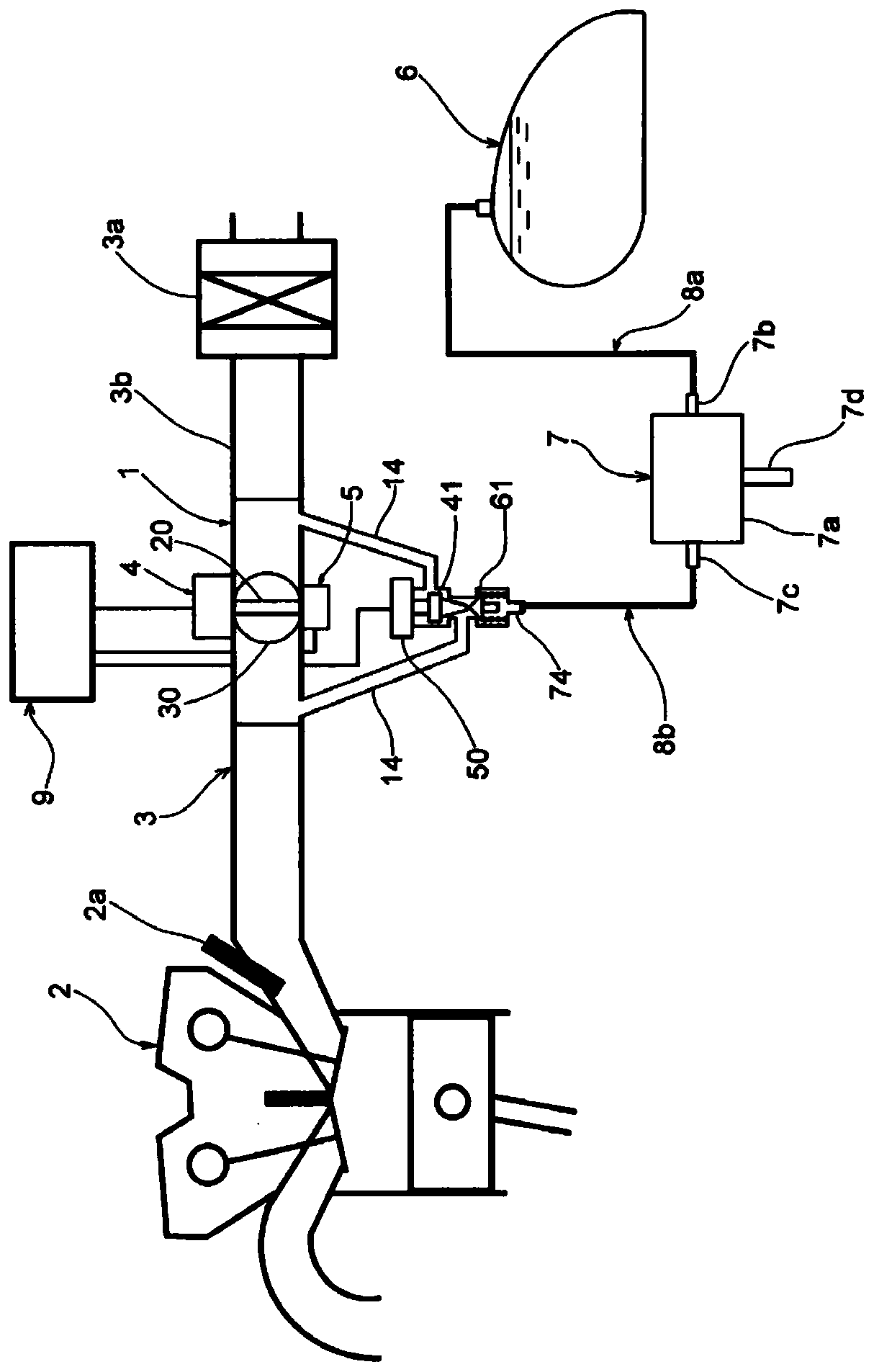
[0043] Such as figure 1 As shown, a throttle device 1 according to one embodiment is assembled in the middle of an intake pipe 3b on the downstream side of an air cleaner 3a in an intake system 3 mounted on an engine 2 of a motorcycle.

[0044] Here, the throttle device 1 is provided with a rotational drive source 4 for rotationally driving the valve shaft 20 of the throttle valve 30 , and a position sensor 5 for detecting the opening position of the throttle valve 30 .

[0045] In addition, in addition to the engine 2 including the injector 2a for fuel injection, and the intake system 3, the motorcycle includes: a fuel tank 6, a metal tank 7, a pipe 8a connecting the fuel tank 6 and the metal tank 7, and connecting the metal tank 7 The pipe 8 b connected to the connector 74 of the throttle device 1 and the control unit 9 .

[0046] The metal tank 7 inc...


PUM


Abstract

This throttle device comprises: a throttle valve (30) for opening and closing a main passage (12); a body (10) having the main passage (12), a secondary passage (14) bypassing the throttle valve (30),and gas passages (15, 14b) for introducing fuel evaporative gas into the main passage (12); a first adjustment valve (41) for adjusting the passage area of the secondary passage (14); a drive source(50) for driving the first adjustment valve (41); and a second adjustment valve (61) for adjusting the passage area of the gas passage (15). The second adjustment valve (61) is driven by the driving force from the drive source (50). Thus, a lower cost and a reduction in size can be achieved while suppressing an increase in specialized components, and fuel evaporative gas can be recovered reliablywithout being discharged to the outside.

Description

technical field [0001] The present invention relates to a throttling device and a fuel evaporated gas recovery system including a structure for introducing fuel evaporated gas in a fuel tank of a motorcycle or the like into an intake system of an engine. Background technique [0002] In conventional vehicles such as motorcycles, in order to prevent the evaporated gas of fuel generated in the fuel tank from being released into the atmosphere, there is known an evaporated fuel treatment device provided with a metal tank ( canister), the charging piping that guides the evaporated gas from the fuel tank to the metal tank, the exhaust piping that guides the evaporated gas from the metal tank to the intake passage of the engine, and the metal tank is discharged by the negative pressure generated in the intake passage. The boil-off gas inside is exhausted into the intake passage (for example, refer to Patent Document 1 and Patent Document 2). [0003] However, in the above-mention...

Claims


Application Information

Patent Timeline
Patent Type & Authority Applications(China)
IPC IPC(8): F02M25/08F02D9/02F02M69/32
CPCF02D9/02F02M25/08F02M69/32Y02T10/12
Inventor 関口眞一川口裕美北冈竜也
Owner MIKUNI CORP
Why Eureka
Try Eureka