Light emitting screen of side light source supplied by AC / DC electricity

A side light source, AC and DC technology, which is applied in the field of low-power side light source light-emitting panels, can solve the problems of short lamp life, large power consumption, and influence on the overall effect of the display card, so as to improve system reliability, stable and reliable performance, The effect of a good display

Inactive Publication Date: 2008-03-12
北京博华三佳技术有限公司
View PDF5 Cites 1 Cited by
  • Summary
  • Abstract
  • Description
  • Claims
  • Application Information

AI Technical Summary

Problems solved by technology

It mainly has the following problems: 1. The scattering angle of the light source is large, and heat is generated, and the effective utilization rate of energy is low
Therefore consumes more power
2. Since the fluorescent tube needs to use a starter, but when the ambient temperature is low, the starter is not easy to start, so the reliability of the light source used is poor
3. Due to the short life of the lamp tube, it usually needs to be replaced once a year at the longest, which is very inconvenient
4. Due to the shadow on the image screen, the overall effect of the display card is affected
[0003] At present, the existing light boxes are generally powered by the power grid. With the increasing shortage of energy, many cities implement limited power supply, resulting in many luminous signs not being displayed normally, and the promotion of urban lighting projects is affected.
[0004] However, the solar LED light-emitting panels developed at present still have the following problems: 1. They can only be powered by direct current. Compared with the light boxes that are currently powered by the grid, they cannot directly use the existing power supply system for transformation and need to be completely replaced. , higher input cost
2. In the current solar LED luminescent panels, the refraction points on the light guide plate are made by digital inkjet technology. In actual use, it is easy to fall off due to long-term sunlight, which affects the luminous effect of the luminescent panel.
3. In the existing LED light-emitting board, the LED light-emitting tube is accommodated in the groove opened on the side of the light guide plate. Since the groove wall has burrs, it cannot be completely smooth, so the burrs on the groove wall It will absorb or scatter the light emitted by the LED light-emitting tube, which will affect the light guiding effect of the light guide plate
4. Since the LED light-emitting tubes accommodated in the groove of the light guide plate are fixed by pouring transparent glue, the LED light-emitting tubes are not fixed when the glue is poured, so in the process of glue filling, due to the LED The luminous tube cannot be stably positioned, resulting in the LED luminous tube not being able to maintain an upright state, making the direction of the light emitted by it inconsistent, resulting in poor luminous effect of the luminous panel

Method used


Image

  • Light emitting screen of side light source supplied by AC / DC electricity
  • Light emitting screen of side light source supplied by AC / DC electricity

Examples


Embodiment Construction

[0018] A detailed description will be given below in conjunction with preferred embodiments of the present invention and accompanying drawings.

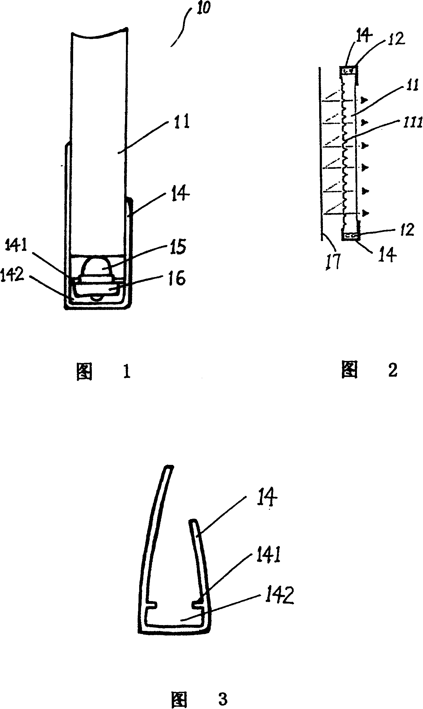
[0019] As shown in Figures 1 to 3, the luminous plate 10 includes a light guide plate 11 and a light source 12. The light guide plate 11 is made of polymethyl methacrylate (Poly Methyl Meth Acrylate), which is an optical grade PMMA light guide plate, which has a certain Thickness, can be made into various shapes. The back of the light guide plate 11 is provided with reticulated refraction grooves 111 made by three-dimensional laser engraving technology. The farther the refraction grooves 111 are from the light source 12, the larger the groove diameter and the sparser the spacing. In this way, the light path closer to the light source is narrower, and the light path farther away is wider, thereby solving the problem of changing a point light source into a surface light source, so that the brightness of the picture displayed by the pre...


PUM


Abstract

The invention relates to an AC-DC lateral-light source light-emitting plate, comprising light guide plate and light source, where the back of the light guide plate is provided with reflecting film, and characterized in that: it also comprises a 'U'-shaped elastic insulating bar, where two sides of the lower part of the insulating bar is provided with salient edges on the inner wall, extending in the direction of the insulating bar; the light source comprises LEDs welded on a circuit board at certain intervals; the circuit board is inserted below the salient edges; the polished end surface of the light guide plate is inserted above the salient edges; the back of the light guide plate is provided with netlike refracting grooves formed by 3D laser carving, where the further the refracting groove is apart from the light source, the larger the groove diameter is and the larger the space is; the power supply input end of the light source is connected with a switching power supply. The invention can be widely applied to highways, city traffic marks, etc.

Description

technical field [0001] The invention relates to a low-power side light source luminescent panel capable of supplying power in two ways of AC and DC. Background technique [0002] Currently used light boxes with light sources are backlight light boxes, most of which use fluorescent tubes and incandescent lamps as the light source on the back of the screen, and irradiate the pattern through transmitted light. It mainly has the following problems: 1. The scattering angle of the light source is large, and heat is generated, and the effective utilization rate of energy is low. Therefore, the power consumption is relatively large. 2. A starter is needed to turn on the fluorescent tube, but when the ambient temperature is low, the starter is not easy to start, so the reliability of the light source used is poor. 3. Due to the short life of the lamp tube, it usually needs to be replaced once a year at the longest, which is very inconvenient. 4. Due to the shadow on the image scre...

Claims


Application Information

Patent Timeline
Patent Type & Authority Patents(China)
IPC IPC(8): G09F13/22
Inventor 王国华
Owner 北京博华三佳技术有限公司
Why Eureka
Try Eureka