Method for producing a coupling on a pipe and device for producing said coupling

一种喇叭口、管子的技术,应用在在管子上加工喇叭口和用于形成喇叭口的装置领域,能够解决泄漏等问题,达到节省材料费用、壁厚增加的效果

Inactive Publication Date: 2008-04-30
WITZIG & FRANK GMBH
View PDF5 Cites 6 Cited by
  • Summary
  • Abstract
  • Description
  • Claims
  • Application Information

AI Technical Summary

Problems solved by technology

The fittings are then subjected to the greatest stress at the flange and in the area of ​​the sealing parts; in the worst case this can lead to leaks
Due to the thin wall thickness, if the bell mouth figure 1 Leakage may occur if the position indicated by "A" in

Method used


Image

  • Method for producing a coupling on a pipe and device for producing said coupling
  • Method for producing a coupling on a pipe and device for producing said coupling

Examples


Embodiment Construction

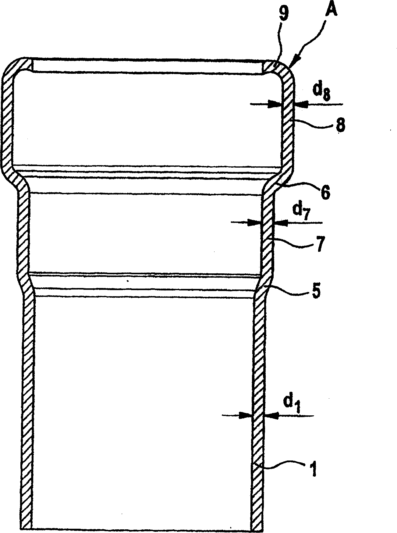
[0016] figure 1 The processed pipe 1 shown in has a wall thickness d1 corresponding to the original pipe wall thickness. After two-step flaring, the tube has a first conical portion 5, an adjoining first cylindrical portion 7 having a wall thickness d7 that decreases in relation to the wall thickness d1 according to the degree of flaring, a second conical portion 6, adjoining The second cylindrical part 8 and the inwardly curved flange 9. The second cylindrical part 8 has a wall thickness d8 which is increased to the required extent by the upsetting step according to the invention before the flange 9 is provided. Wall thickness d8 should be at least equal to wall thickness d7. It has even been found to be advantageous to increase said wall thickness to wall thickness d1.

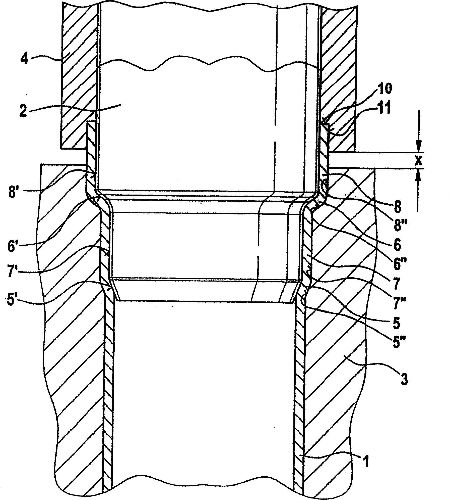
[0017] exist figure 2 , the multi-step flaring tool 2 has been pressed into the pipe end in the axial direction. The shape of the flare with sections 5 to 8 is formed internally by sections 5' to 8' of...


PUM


Abstract

The invention relates to a method for producing a coupling on a pipe (1), preferably consisting of copper or steel or Cu-, Ni-, Fe-alloys, by a preferably graduated or one-stage expansion of the pipe end to create a much larger difference in diameter, an expansion tool (2) being introduced axially into the end of the pipe. The invention is characterised in that when and / or once the expansion tool (2) has been introduced into the pipe end the region of the pipe end that is to be or has been expanded is completely or partially compressed by a force acting axially on said pipe end, whereby the external diameter of the pipe end that is to be processed is delimited by one or more shaping jaws (3) that completely or partially surround the pipe end. The invention also relates to a device for producing a coupling on a pipe end according to said method.

Description

technical field [0001] The present invention relates to a process for flaring tubes, preferably made of copper or steel or alloys of Cu, Ni and Fe, by preferably forming the tube ends in a multi-step or one-step flaring with a large abrupt change in diameter method. To achieve said flaring, the pipe end is introduced axially into a flaring tool. The invention also relates to a device for machining such a type of bell mouth. Background technique [0002] When machining copper or steel fittings from the pipe, it is preferred to form the flare of the pipe end by stepwise flaring the pipe sections. In the process of flaring the tube, at each necessary step, the wall thickness is reduced. For example, it has been found that where the nominal width of the pipe is greater than 50 mm and the wall thickness is 2.7 mm, the wall thickness is only 2.4 mm after two steps of flaring. In the final flaring step where the thinnest wall thicknesses occur, the pipe ends are generally flang...

Claims


Application Information

Patent Timeline
Patent Type & Authority Patents(China)
IPC IPC(8): B21D41/02
CPCB21D41/02
Inventor W·威格纳(琼)W·鲍尔
Owner WITZIG & FRANK GMBH
Why Eureka
Try Eureka