
Optical mouse capable of improving spotlight effect

An optical mouse and light technology, applied in the field of optical mouse, can solve problems such as weak light intensity and achieve the effect of improving sensitivity

Inactive Publication Date: 2008-05-28
PIXART IMAGING INC
View PDF3 Cites 0 Cited by
  • Summary
  • Abstract
  • Description
  • Claims
  • Application Information

AI Technical Summary

Problems solved by technology

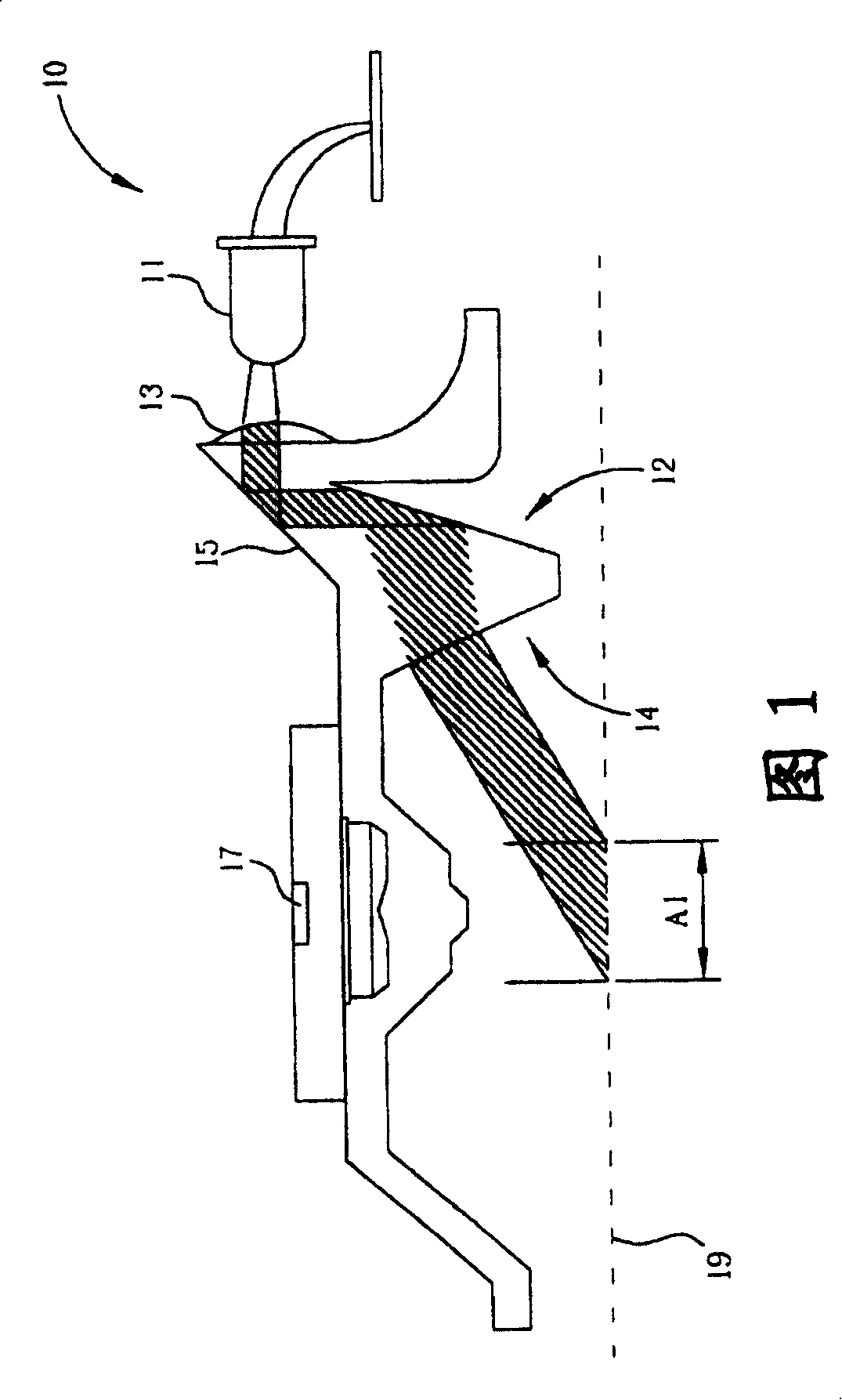
If you encounter an environment with poor light reflection or easy scattering, for example, when working on a glass mat or a table with too bright a surface, because the ambient background light is strong, and the beam area A1 projected to the application surface 19 is relatively large, the optical The intensity of the light received by the mouse 10 is relatively weak. At this time, the optical mouse 10 is likely to misjudge the unevenness of the application surface 19

Method used


Image

  • Optical mouse capable of improving spotlight effect
  • Optical mouse capable of improving spotlight effect
  • Optical mouse capable of improving spotlight effect

Examples


Embodiment Construction

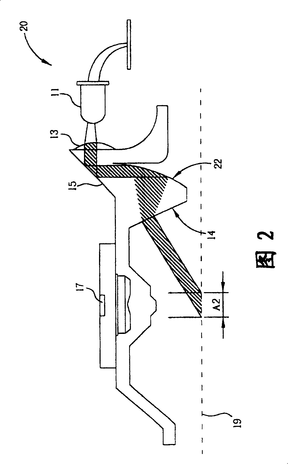
[0019] Please refer to FIG. 2, which is a schematic diagram of the optical mouse 20 of the present invention. The optical mouse 20 includes a light source 11, a lens 13, a reflective surface 15, a circular arc surface 22, a penetrating surface 14 and a light sensor 17. The light source 11 is used to project light, the convex lens 13 is used to focus the light, and the reflective surface 15, the arc surface 22 and the penetrating surface 14 are used to guide the light to guide the light generated by the light source 11 to the application surface 19. The light sensor 17 receives the light reflected by the application surface 19 to control the operation of the optical mouse 20.

[0020] As shown in the light path in FIG. 2, the light source 11 projects light, which first forms a light beam through the action of the convex lens 13, and is directed to the reflective surface 15. Then, the light beam directed to the reflecting surface 15 travels downward to the arc surface 22 through the...


PUM


Abstract

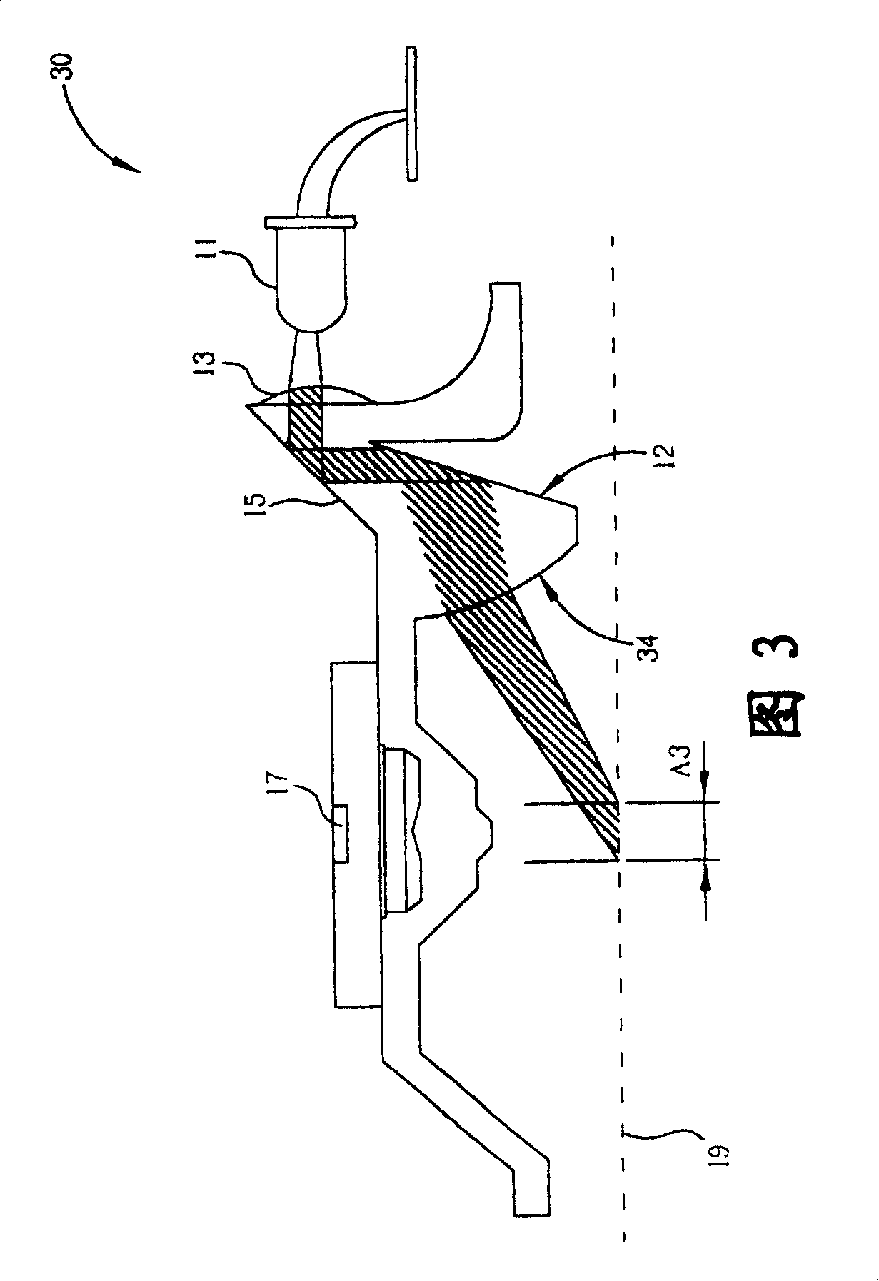
The invention relates to an optical mouse for improving the focusing effect, which comprises: a light source, a lens, first reflective surface, second reflective surface, one arc surface, and one optical sensor, wherein the incident light of light source is focused by the lens to be reflected by the first and second reflective surfaces, to be focused by the arc surface, to be projected to one application surface; and the reflected light will be received by optical sensor to control the operation of optical mouse.

Description

Technical field [0001] The invention provides an optical mouse that can improve the light-gathering effect, especially an optical mouse that uses a circular arc surface to improve the light-gathering effect. Background technique [0002] Please refer to FIG. 1, which is a schematic diagram of the internal structure of a known optical mouse 10. The optical mouse 10 includes a light source 11, a convex lens 13, reflective surfaces 12 and 15, a penetrating surface 14 and a light sensor 17. The light source 11 is used to generate light, the convex lens 13 is used to focus the light, and the reflective surfaces 12 and 15 and the penetrating surface 14 are used to guide the light to guide the light generated by the light source 11 to an application surface 19. The light sensor 17 receives the light reflected by the application surface 19 to control the operation of the optical mouse 10. [0003] As shown in the light path in FIG. 1, the light source 11 is used to generate light. The li...

Claims


Application Information

Patent Timeline
Patent Type & Authority Patents(China)
IPC IPC(8): G06F3/033G06F3/0354
Inventor 简茂雄
Owner PIXART IMAGING INC
Learn More