Method for realizing digital relay protection anti-time limit characteristic

A technology of relay protection and realization method, which is applied to emergency protection circuit devices, automatic disconnection emergency protection devices, electrical components, etc., can solve the problems of large amount of real-time calculation, high calculation speed requirements, and difficulty in implementation.

Inactive Publication Date: 2008-05-28
HARBIN INST OF TECH
View PDF5 Cites 0 Cited by
  • Summary
  • Abstract
  • Description
  • Claims
  • Application Information

AI Technical Summary

Problems solved by technology

[0003] The purpose of the present invention is to provide a method for realizing the inverse time-limit characteristic of digital relay protection that does not require high computing speed, real-time calculation amount is small, and is easy to implement, so as to overcome the limitation of existing methods on relay protection. The protective device requires high computing speed, large amount of real-time calculation, and difficult to realize, etc.

Method used


Image

  • Method for realizing digital relay protection anti-time limit characteristic
  • Method for realizing digital relay protection anti-time limit characteristic
  • Method for realizing digital relay protection anti-time limit characteristic

Examples


specific Embodiment approach 1

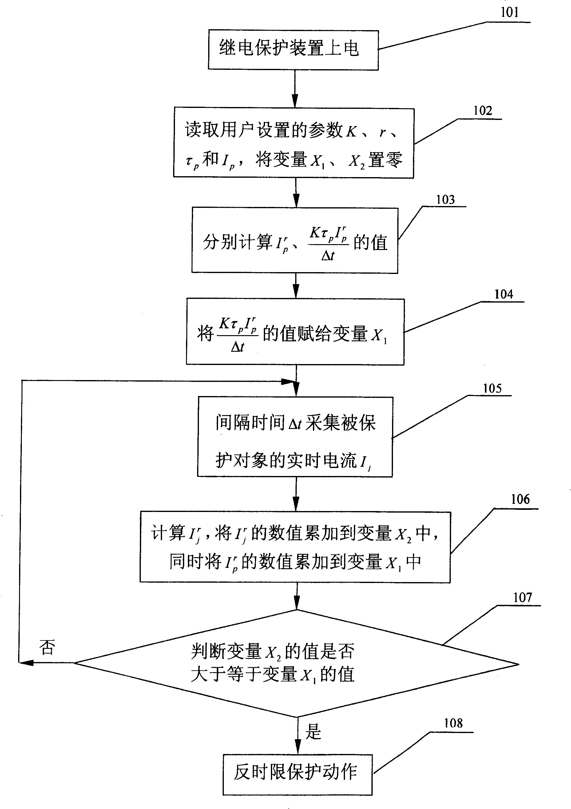
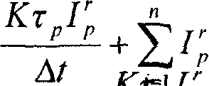
[0005] Specific embodiment one: the following combination figure 1 The present embodiment will be specifically described. The steps of this embodiment are as follows: the relay protection device is powered on 101; the parameters K, r, τ set by the user are read p and I p , the variable X 1 , X 2 Set to zero 102; calculate I separately p r , value of 103; will assign the value to the variable X 1 104; the interval time Δt collects the real-time current I of the protected object j 105; Calculate I j r , then set I j r The value of is accumulated into the variable X 2 , while placing I p r The value of is accumulated into the variable X 1 Medium 106; Judgment variable X 2 Whether the value of is greater than or equal to the variable X 1 The value of 107; if the result of step 107 is no, return to the starting end of step 105; if the result of step 107 is yes, then the inverse time limit protection action 108.

[0006] After the relay protection device is po...

specific Embodiment approach 2

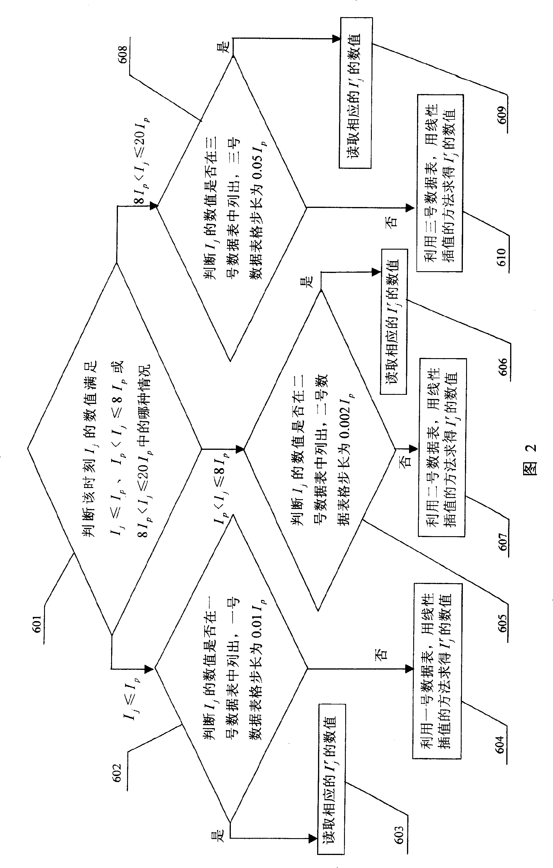
[0013] Embodiment 2: This embodiment is about Embodiment 1 in step 106. j r numerical calculation method. I j r The numerical calculation method is divided into two cases. If r=1 or r=2, the relay protection device can directly perform mathematical calculation; if r=0.02, it is difficult for the relay protection device to directly perform mathematical calculation, so look-up table is used. A method combined with piecewise linear interpolation. In the following, the first embodiment when r=0.02 is described in detail with reference to FIG. 2. In step 106, I j r The calculation process of the value: determine the moment I j The value of satisfies I j ≤I p , I p j ≤8I p or 8I p j ≤20I p Which of the cases 601; if I j ≤I p , that is, the actual current of the protected object is (0-1)I p , then judge I j Is the value listed in the No. 1 data sheet, the No. 1 data sheet step size is 0.01I p , a total of 101 values, these 101 I j r The values ​​of , respectively, ...


PUM


Abstract

This invention relates to digital relay protection reverse limited characteristics realization method, which comprises the following steps: Switching on relay protective device; reading user set parameters to turn variable X1 to X2; computing (Ktau pIrp) / delta t and denoting it on variable X1; collecting current 1j with isolation time delta t; computing 1jr and summing it to variable X2; summing Ipr to variable X1; judging whether variable X2 larger than variable X1; if yes, then processing reverse protective operation, if not then restarting sampling, computing, comparing or judging.

Description

technical field [0001] The invention belongs to an overcurrent protection method of a relay protection device, in particular to a method for realizing the inverse time-limit characteristic of a digital relay protection device. Background technique [0002] The accurate calculation of the action time of the inverse time characteristic (current / time characteristic) of the relay protection device can ensure the timely and reliable action of the relay protection device under the fault condition of the protected objects such as power equipment or lines, which is important for the effective protection of power equipment or lines. significance. In the existing method for realizing the inverse time characteristic of digital relay protection, the calculation of the action time of the inverse time characteristic often uses the ratio of the real-time current of the protected object to the rated current as the calculation basis. The disadvantage of this method is that : The amount of r...

Claims


Application Information

Patent Timeline
Patent Type & Authority Patents(China)
IPC IPC(8): H02H3/28H02H3/00
Inventor 佟为明林景波张文义李凤阁赵志衡李中伟
Owner HARBIN INST OF TECH
Why Eureka
Try Eureka