Supercharge Your Innovation With Domain-Expert AI Agents!

Method for restricting poly-silicon pattern

A technology of polysilicon and polysilicon layer, which is applied in the direction of electrical components, semiconductor/solid-state device manufacturing, circuits, etc., to achieve the effect of improving uniformity

Active Publication Date: 2008-06-04
UNITED MICROELECTRONICS CORP
View PDF5 Cites 0 Cited by
  • Summary
  • Abstract
  • Description
  • Claims
  • Application Information

AI Technical Summary

Problems solved by technology

When carrying out the etching process, since the etching rate of the doped polysilicon layer 14a is much higher than that of the undoped polysilicon layer 14b, the two sides of the doped polysilicon layer 14a are caused to have side erosion 18, so the N-type / P-type cannot be made The profile of the polysilicon layer is close to the critical line width after etching

Method used


Image

  • Method for restricting poly-silicon pattern
  • Method for restricting poly-silicon pattern
  • Method for restricting poly-silicon pattern

Examples


Embodiment Construction

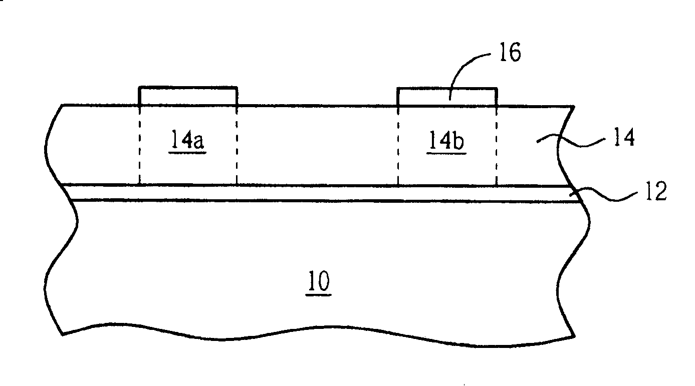
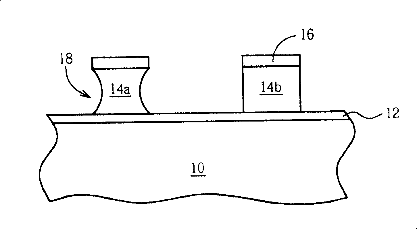
[0026] Please refer to Figure 5 to Figure 8 , Figure 5 to Figure 8 A method of defining a polysilicon pattern for the present invention. like Figure 5 As shown, the present invention provides a substrate 50, such as a silicon substrate, and then sequentially forms a gate oxide layer 52, a polysilicon layer 54, and a patterned photoresist masking layer 60 on the substrate 50, such as photoresist resist layer. In addition, the present invention needs to form a hard mask layer 56 between the photoresist mask layer 60 and the polysilicon layer 54, and optionally uses a bottom anti-reflection layer 58 and / or other material layers to form a composite The shielding material layer, and the composite shielding material layer including the hard masking layer 56 and the bottom anti-reflection layer 58 have been patterned to define a plurality of cavities on the surface of the polysilicon layer 54 .

[0027] The polysilicon layer 54 includes different regions (not shown) used to de...


PUM


Abstract

The provided method to limit polysilicon pattern comprises: forming a polysilicon on a substrate, and a pattern screen layer on top; taking the first etching for the exposed polysilicon layer to form multiple concave holes, stripping the screen layer with gas without O2; finally, etching secondly to let the holes up to substrate surface.

Description

technical field [0001] The present invention relates to a method for defining a polysilicon pattern, in particular to a method for etching a polysilicon layer. Background technique [0002] With the advancement of semiconductor process technology, it is a current trend to integrate N-type polysilicon and P-type polysilicon processes to obtain gate structures with different electrical properties, thereby satisfying different requirements of semiconductor devices. Since the dopants required for N-type polysilicon and P-type polysilicon are different, the two also have different results in terms of process performance. For example, as the line width of semiconductor devices continues to shrink, the N-type / P The profile of the type polysilicon layer, the after-etch-inspection critical dimension (AEI CD) line width, and the uniformity of the gate oxide layer remaining after etching have all developed to bottlenecks. Therefore, how to provide an ideal method to define the pattern...

Claims


Application Information

Patent Timeline
Patent Type & Authority Patents(China)
IPC IPC(8): H01L21/306H01L21/28H01L21/768
Inventor 周珮玉陈东郁
Owner UNITED MICROELECTRONICS CORP
Features
  • R&D
  • Intellectual Property
  • Life Sciences
  • Materials
  • Tech Scout
  • Unparalleled Data Quality
  • Higher Quality Content
  • 60% Fewer Hallucinations
Learn More