High-voltage pulse resistance voltage divider

A resistor divider and high-voltage pulse technology, which is applied in the field of performance devices, can solve the problems of increasing the overall lateral size of the voltage divider, and achieve the effect of simple structure and reduced step response time

Inactive Publication Date: 2008-07-02
SOUTHEAST UNIV
View PDF6 Cites 0 Cited by
  • Summary
  • Abstract
  • Description
  • Claims
  • Application Information

AI Technical Summary

Problems solved by technology

The former will greatly increase the overall lateral size of the voltage divider, the latter will be limited by the operating voltage

Method used


Image

  • High-voltage pulse resistance voltage divider

Examples


Embodiment Construction

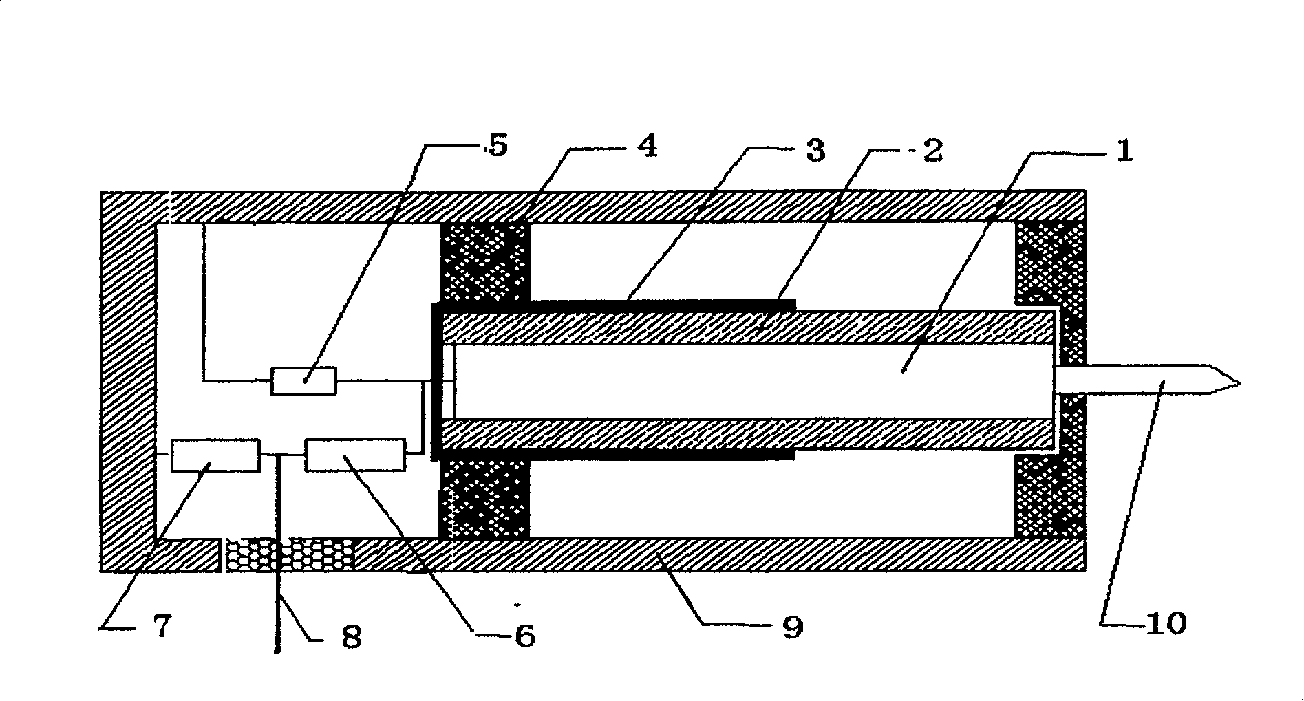
[0013] The outer shield 9 of the high-voltage pulse resistor divider of the present invention is a hollow tube, the outer shield 9 is provided with a first-stage high-voltage arm resistor 1, and the first-stage high-voltage arm resistor 1 is covered with an insulating sleeve Tube 2, sleeve electrode 3 is sleeved at one end of the insulating sleeve 2, and both ends of the insulating sleeve 2 are respectively supported by the high-voltage arm bracket 4 in the outer shield 9 and connected to the outer end of the first-stage high-voltage arm resistor 1. There is a high-voltage input pole 10, the inner end of the first-stage high-voltage arm resistor 1 is connected to the sleeve electrode 3. A first-stage low-voltage arm resistor 5 and a second-stage high-voltage arm are provided between the bottom of the outer shield 9 and the high-voltage arm bracket 4. Arm resistor 6, second-stage low-voltage arm resistor 7, voltage divider output electrode 8. One end of the first-stage low-voltage ...


PUM


Abstract

The invention relates to a high pressure pulse resistance voltage divider which can reduce the reaction time of the resistance voltage divider and improve the function of the voltage divider. The outer shield radar dome (9) of the voltage divider is a hollow pipe-type which possesses a first stage high pressure arm resistance (1); the insulated bushing (2) is covered out the first stage high pressure arm resistance (1); the pad electrode (3) is covered on one end of the insulated bushing (2); the high pressure arm frame (4) on the two ends of the insulated bushing (2) is supported inside the outer shield radar dome (9); the high pressure input end (10) is connected with the out end of the first stage high pressure arm resistance; the pad electrode (3) is connected with the inner end of the first stage high pressure arm resistance; the first stage low pressure arm resistance, the second stage high pressure arm resistance, the second stage low pressure arm resistance, and the divider output end are positioned between the outer shield radar dome (9) and the high pressure arm frame (4).

Description

Technical field [0001] The invention is a device that can effectively reduce the response time of the step response of the resistance voltage divider and improve the performance of the voltage divider, is suitable for the measurement of high voltage pulses, and belongs to the technical field of high voltage measurement. Background technique [0002] The error generated by the resistance voltage divider when measuring the impulse voltage is related to the product of the resistance value and the stray capacitance to ground. Therefore, the error can be reduced by reducing the resistance and reducing the stray capacitance to the ground. However, if the resistance is too small, on the one hand, it will have an impact on the generator's shock wave. On the other hand, it is difficult to dampen the oscillation between the residual inductance and the stray capacitance, and the resulting step response will produce a higher overshoot. Therefore, reducing the measurement error is mainly focu...

Claims


Application Information

Patent Timeline
Patent Type & Authority Patents(China)
IPC IPC(8): G01R15/04
Inventor 蒋全兴陈炜峰周忠元景莘慧
Owner SOUTHEAST UNIV
Why Eureka
Try Eureka