Supercharge Your Innovation With Domain-Expert AI Agents!

Cylindrical part

A technology of cylindrical parts and cylindrical parts, which is applied in the direction of tubular articles, optical elements, thin material processing, etc.

Inactive Publication Date: 2008-07-16
OLYMPUS CORP
View PDF4 Cites 1 Cited by
  • Summary
  • Abstract
  • Description
  • Claims
  • Application Information

AI Technical Summary

Problems solved by technology

However, in the state of FIG. 26 , since the zoom frame 105 is fitted into the larger portion of the diameter deformation near the end 104b of the cam frame 104, the radial gap S1 between the zoom frame 105 and the cam frame 104 increases, At the same time, a fitting gap S2 between the cam follower 106 and the cam groove 104c is also generated.

Method used


Image

  • Cylindrical part
  • Cylindrical part
  • Cylindrical part

Examples


Embodiment Construction

[0046] Embodiments of the present invention will be described below using the drawings.

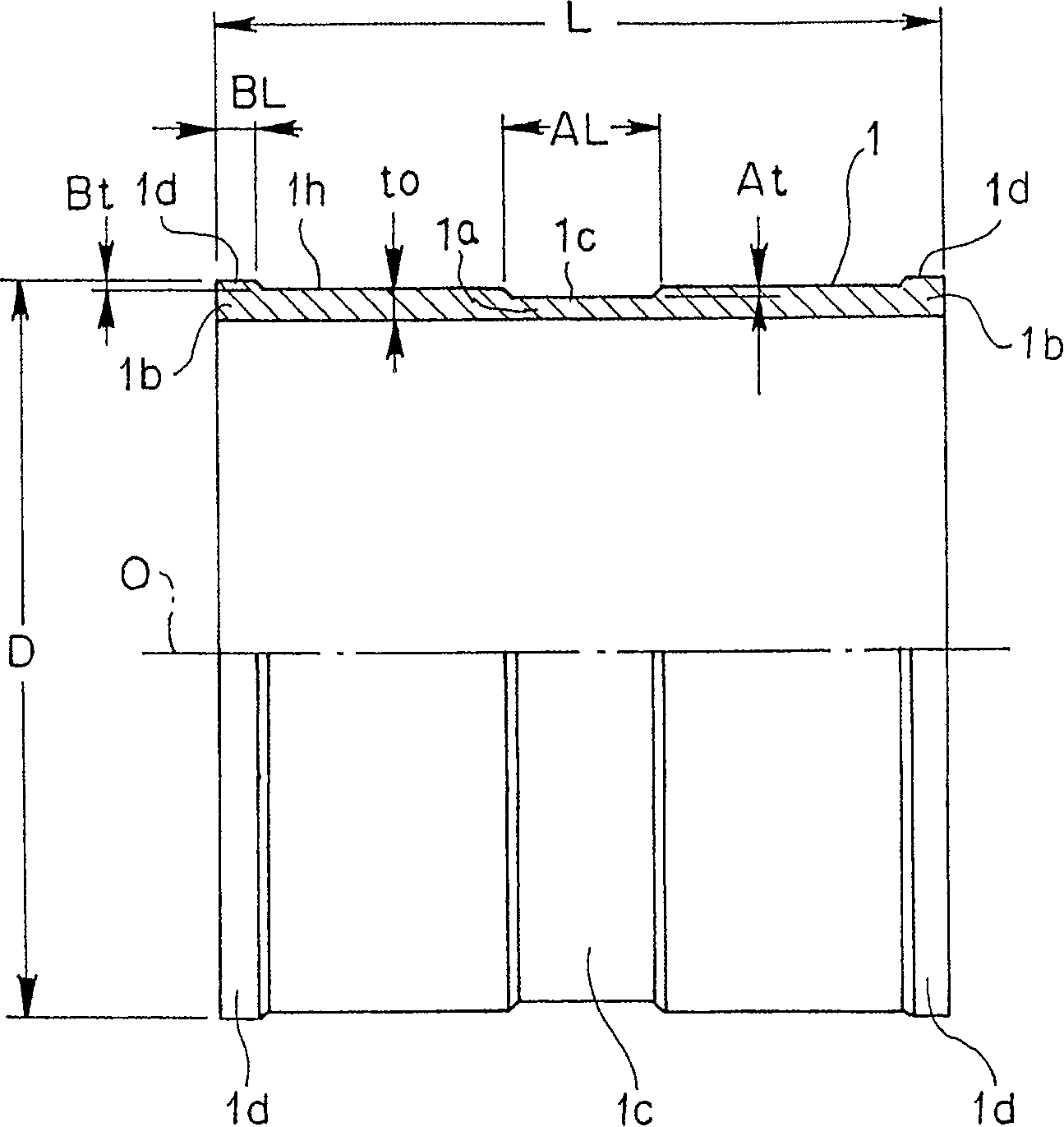
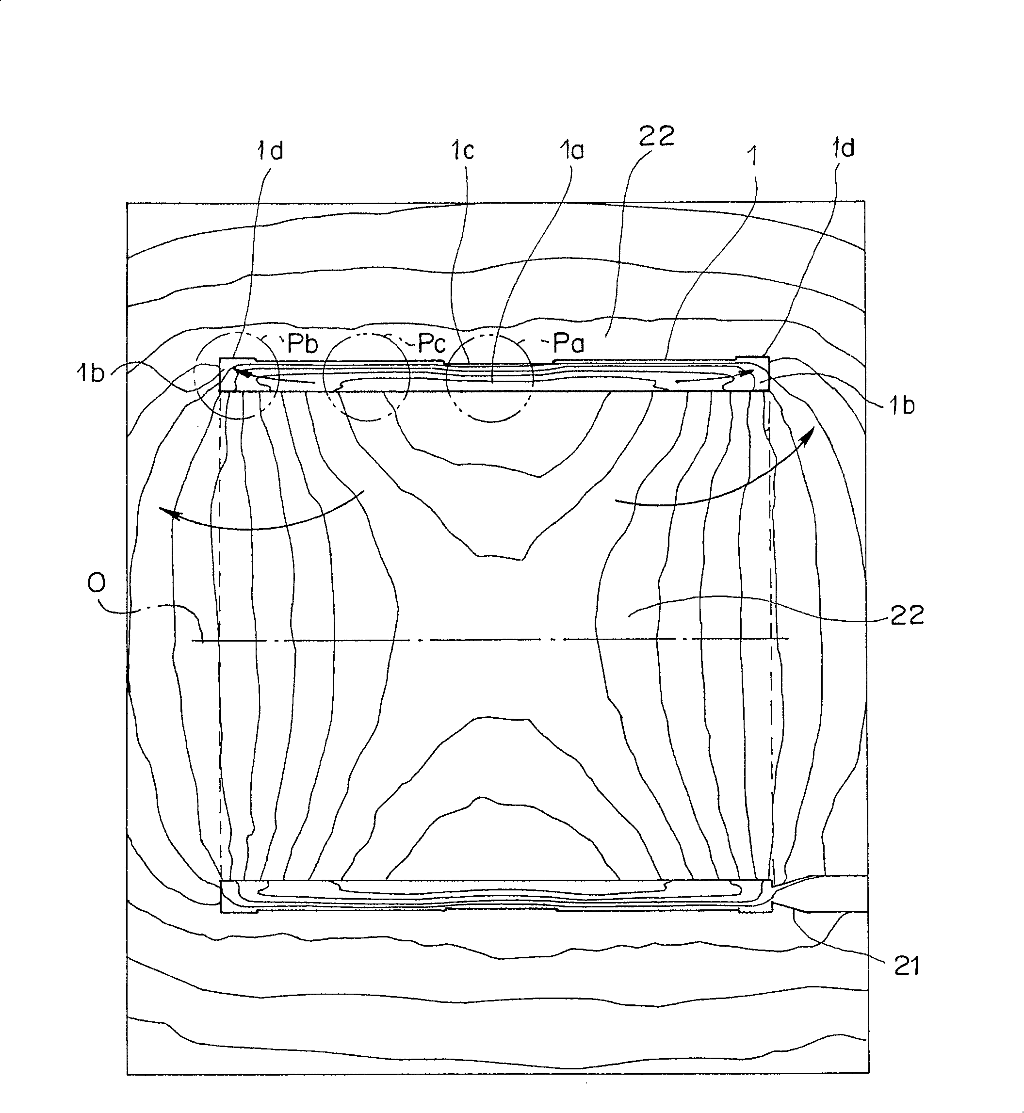
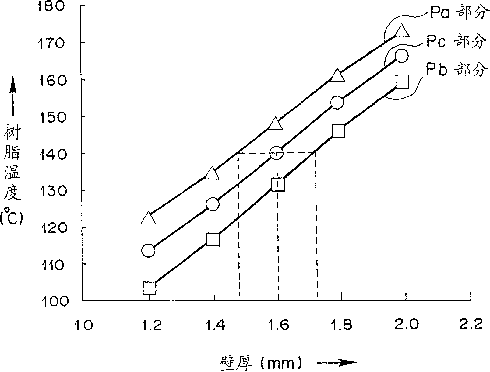
[0047] figure 1 It is a side view showing the upper half of the cylindrical member which is the cylindrical member of the first embodiment of the present invention in section. figure 2 It is a diagram showing the temperature distribution of the mold and the cylindrical member when the cylindrical member is molded and when the resin filling is completed (the direction of the arrow in the figure indicates the direction in which the temperature on the isotherm decreases). image 3 to represent figure 2 A graph showing the relationship between the wall thickness (horizontal axis) of the main part of the cylindrical member and the resin temperature (the temperature of each main part at the end of filling, the vertical axis). Figure 4 This is an enlarged view showing the deformed state of the above-mentioned cylindrical member molding, and is a side view showing the upper half in section. ...


PUM

PropertyMeasurementUnit
lengthaaaaaaaaaa
thicknessaaaaaaaaaa

Abstract

A cylindrical member, which is a cylindrical part molded by injection molding, has a cylindrical shape having a substantially uniform thickness in a circumferential direction and whose both end-face edge portions are opened, in which a band-state groove portion for forming a thin portion along the outer circumference of a cylindrical center portion forming a cylindrical portion and a thick edge portion along the outer circumference of the both end-face edge portions are provided. Since the band-state groove portion and the thick edge portion are provided, the temperature of the cylindrical member does not become relatively high at the center portion, while the temperature of the end-face portions does not become relatively low at molding, and molding contraction rates are made uniform in general and the cylindrical member with good form accuracy can be obtained.

Description

technical field [0001] The present invention relates to an injection molded cylindrical part. Background technique [0002] In conventional molding techniques, when a cylindrical resin part is produced by injection molding, the diameter near the center tends to shrink and become smaller. The reason why the central portion becomes smaller in this way will be described using FIGS. 23 and 24 . [0003] FIG. 23 is a diagram showing the temperature distribution of the mold 101 and the cylindrical member 103 at the time of completion of resin filling in the form of isotherms during molding of a conventional resin cylindrical member. The direction of the arrow in the figure shows the direction in which the temperature on the isotherm line becomes lower. [0004] When the molten resin material is filled into the cavity of the metal mold 101, the heat of the resin is transferred into the metal mold, so that the temperature of the metal mold 101 rises. At this time, since there are...

Claims


Application Information

Patent Timeline
Patent Type & Authority Patents(China)
IPC IPC(8): G02B7/04
CPCB29C45/0025B29L2023/00B29C2045/0043Y10T428/139Y10T428/24777
Inventor 广濑量哉
Owner OLYMPUS CORP
Features
  • R&D
  • Intellectual Property
  • Life Sciences
  • Materials
  • Tech Scout
  • Unparalleled Data Quality
  • Higher Quality Content
  • 60% Fewer Hallucinations
Learn More