

Multipurpose LED support
An LED bracket and multi-functional technology, applied in electrical components, electrical solid devices, circuits, etc., can solve problems such as the inability to use single-electrode LED chips, achieve diverse electrical connections, solve automated production problems, and solve heat conduction problems. Effect
- Summary
- Abstract
- Description
- Claims
- Application Information
AI Technical Summary
Problems solved by technology
Method used
Image

Examples
Embodiment 1
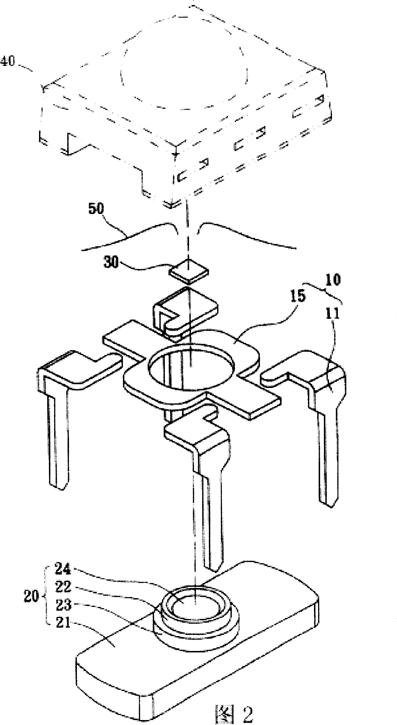
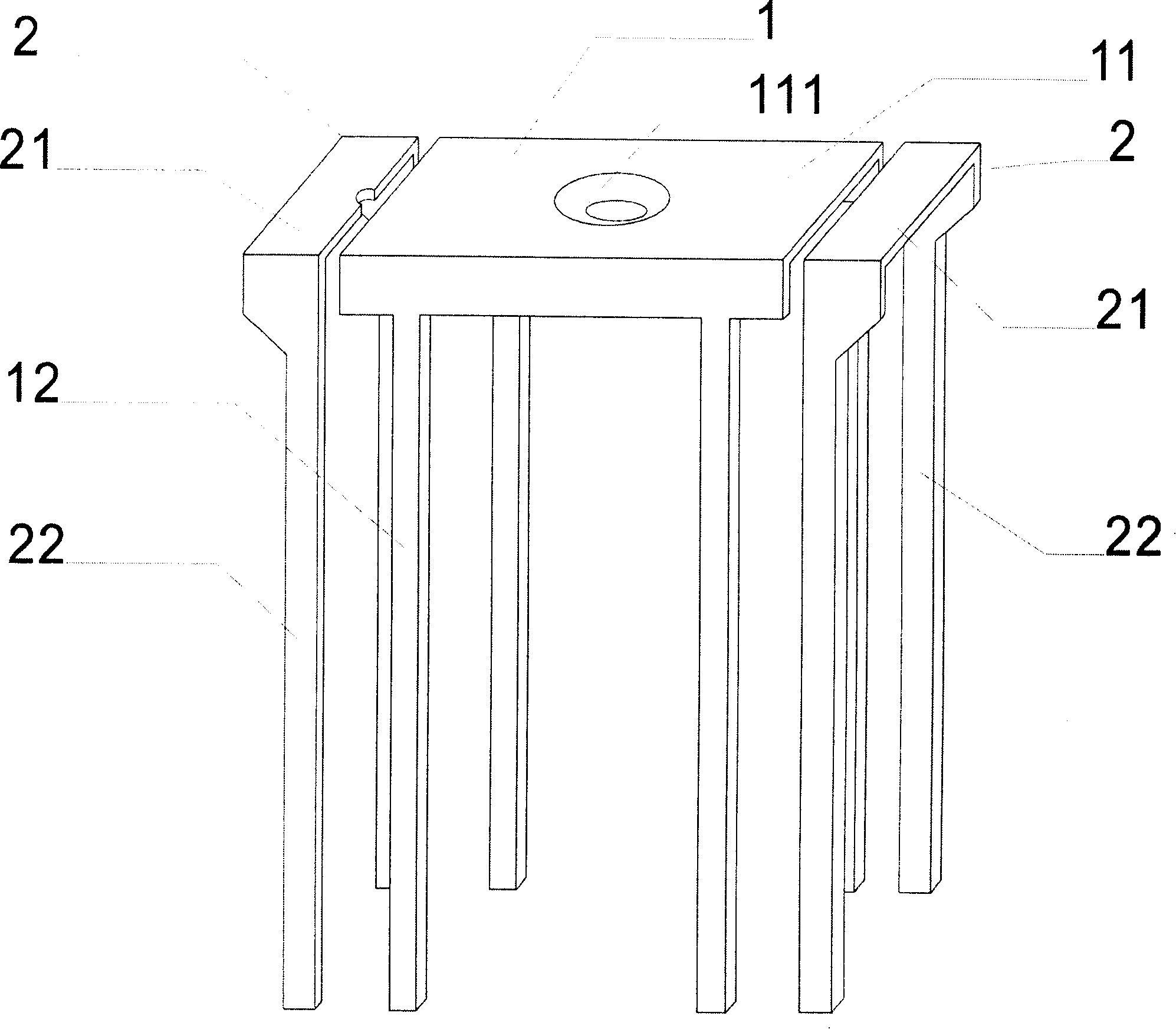
[0019] Such as image 3 and Figure 4 As shown, the multi-functional LED bracket described in this embodiment is composed of a main bracket 1 and two auxiliary brackets 2 located on both sides of the main bracket. The main bracket 1 is composed of a rectangular flat part 11 and two rows of four pins 12 integrally extending downward from the rectangular flat part. There is a concave part 111 in the middle of the rectangular flat part 11. A trapezoid whose base is greater than the lower base. The sub-support 2 is composed of a rectangular planar portion 21 and two pins 22 integrally extending downward from the rectangular planar portion. The pins 12 of the main support and the pins 22 of the auxiliary support are arranged in a split double-in-line structure. The rectangular plane part 11 of the main support and the rectangular plane part 21 of the auxiliary support are on the same horizontal plane.
[0020] The plane part 21 of each sub-support can be automatically cut off a...
Embodiment 2
[0024] Such as Figure 5 As shown, the multi-functional LED bracket described in this embodiment is composed of a main bracket 1 and two auxiliary brackets 2 located on both sides of the main bracket. The main bracket 1 is composed of a rectangular flat part 11 and two pins 12 extending downward from the rectangular flat part. There is a concave part 111 in the middle of the rectangular flat part 11. A trapezoid whose side is greater than the lower base. The sub-support 2 is composed of a rectangular planar portion 21 and two pins 22 integrally split downward from the rectangular planar portion. The pins 12 of the main support and the pins 22 of the auxiliary support are arranged in a split double-in-line structure. The rectangular plane part 11 of the main support and the rectangular plane part 21 of the auxiliary support are on the same horizontal plane.
[0025] The use effect of this embodiment is the same as that of Embodiment 1, and will not be repeated here.
Embodiment 3
[0027] Such as Figure 6 As shown, the multi-functional LED bracket described in this embodiment is composed of a main bracket 1 and four auxiliary brackets 2 located on both sides of the main bracket. The main bracket 1 is composed of a rectangular flat part 11 and four pins 12 extending downward from the rectangular flat part. There is a concave part 111 in the middle of the rectangular flat part 11. A trapezoid whose side is greater than the lower base. Each sub-support 2 is composed of a rectangular planar portion 21 and a pin 22 integrally extending downward from the rectangular planar portion. The pins 12 of the main support and the pins 22 of the auxiliary support are arranged in a split double-in-line structure. The rectangular plane part 11 of the main support and the rectangular plane part 21 of the auxiliary support are on the same horizontal plane.
[0028] The use effect of this embodiment is the same as that of Embodiment 1, and will not be repeated here.
[...
PUM
 Abstract
Description
Claims
Application Information