Electrical connector with electrically shielded terminals

a technology of shielding terminals and electrical connectors, applied in the direction of coupling device connections, coupling device details, coupling protective earth/shielding arrangements, etc., can solve the problems of introducing more signal noise and generating undesired signal propagation modes

Active Publication Date: 2010-02-25
TYCO ELECTRONICS LOGISTICS AG (CH)
View PDF35 Cites 68 Cited by
  • Summary
  • Abstract
  • Description
  • Claims
  • Application Information

AI Technical Summary

Benefits of technology

[0005]In one embodiment, an electrical connector includes a housing and a lead frame held by the housing. The lead frame includes a terminal extending along a length between a mating end portion and a mounting end portion. The terminal is at l

Problems solved by technology

However, increasing signal speed and/or density may introduce more signal noise, commonly referred to as crosstalk, between terminals within a single lead frame and/or between the t

Method used


Image

  • Electrical connector with electrically shielded terminals
  • Electrical connector with electrically shielded terminals
  • Electrical connector with electrically shielded terminals

Examples


Embodiment Construction

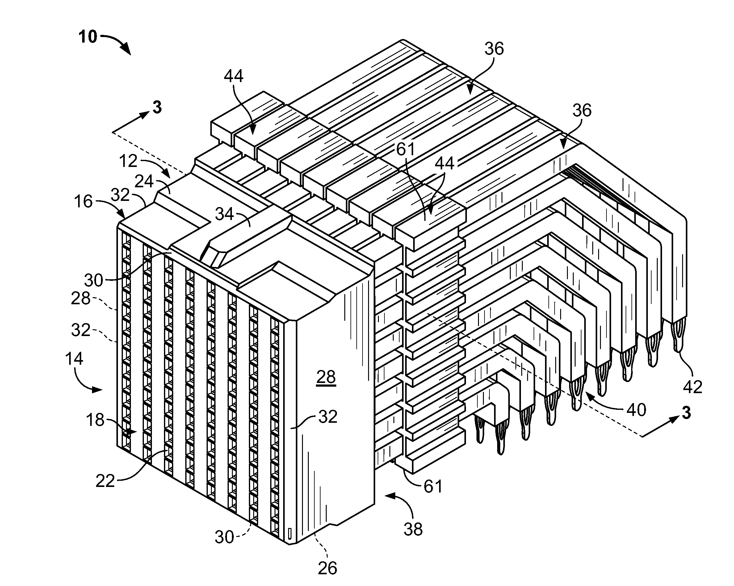
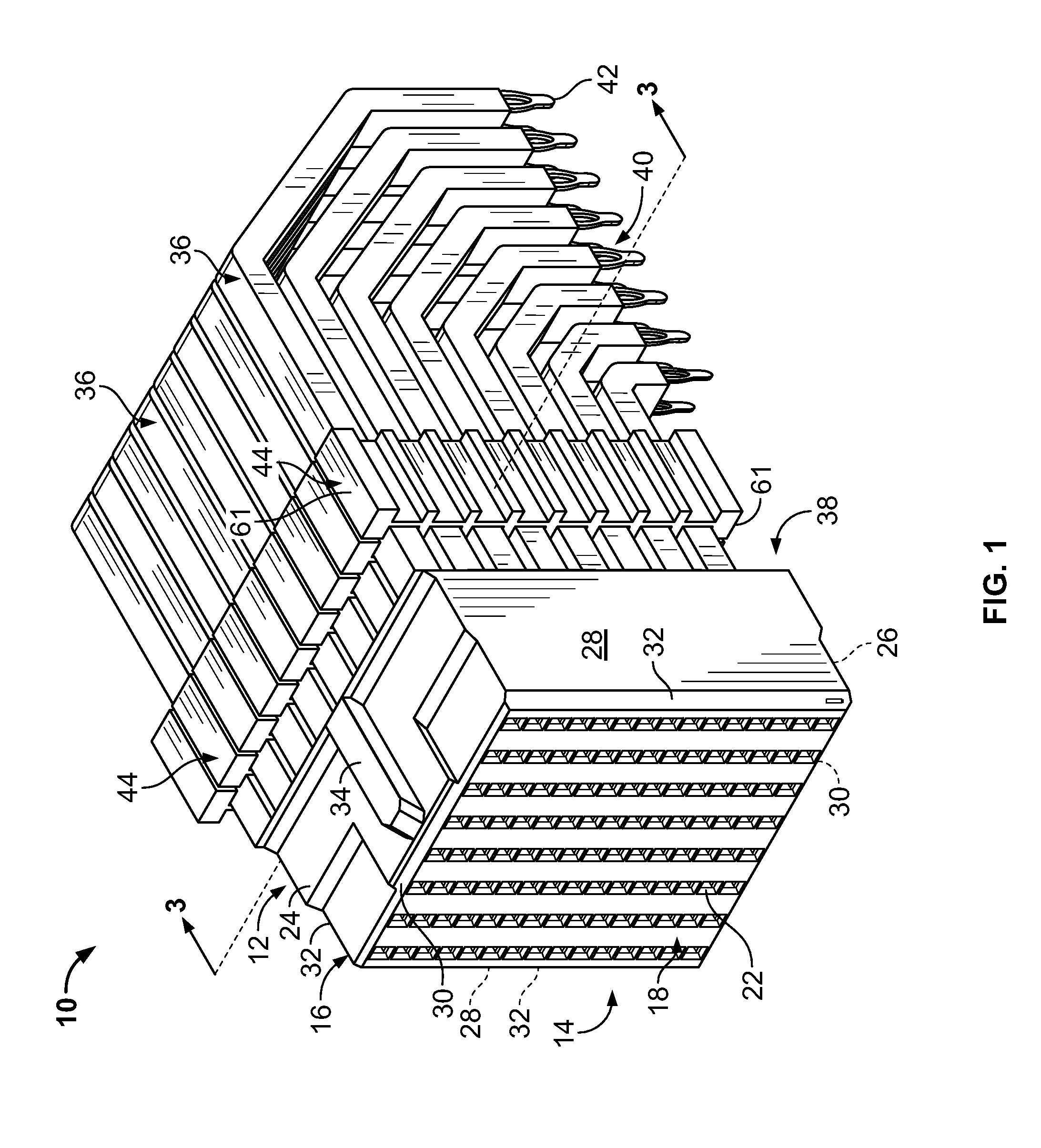
[0018]FIG. 1 is a perspective view of an exemplary embodiment of an electrical connector 10. The connector 10 includes a dielectric housing 12 having a forward mating end 14 that includes a shroud 16 and a mating face 18. The mating face 18 includes a plurality of mating contacts 20 (shown in FIGS. 4 and 5), such as, for example, contacts within contact cavities 22, that are configured to receive corresponding mating contacts (not shown) from a mating connector (not shown). The shroud 16 includes an upper surface 24 and a lower surface 26 between opposite sides 28. The upper and lower surfaces 24 and 26, respectively, each includes an optional chamfered forward edge portion 30. The sides 28 each include optional chamfered side edge portions 32. Optionally, an alignment rib 34 is formed on the upper shroud surface 24 and lower shroud surface 26. The chamfered edge portions 30 and 32 and the alignment ribs 34 cooperate to bring the connector 10 into alignment with the mating connector...


PUM


Abstract

An electrical connector includes a housing and a lead frame held by the housing. The lead frame includes a terminal extending along a length between a mating end portion and a mounting end portion. The terminal is at least partially surrounded by a dielectric core extending a length along at least a portion of the length of the terminal. The dielectric core is metallized such that the core is at least partially surrounded by an electrically conductive shell.

Description

BACKGROUND OF THE INVENTION[0001]The subject matter described and / or illustrated herein relates generally to electrical connectors, and more particularly, to lead frames for electrical connectors.[0002]In a traditional approach for interconnecting circuit boards, one circuit board serves as a back plane and the other as a daughter board. The back plane typically has a connector, commonly referred to as a header, that includes a plurality of signal pins or contacts which connect to conductive traces on the back plane. The daughter board connector, commonly referred to as a receptacle, also includes a plurality of contacts or pins. Typically, the receptacle is a right angle connector that interconnects the back plane with the daughter board so that signals can be routed therebetween. The right angle connector typically includes a mating face that receives the plurality of signal pins from the header on the back plane, and contacts that connect to the daughter board.[0003]Some right an...

Claims


Application Information

Patent Timeline
IPC IPC(8): H01R13/648
CPCH01R13/65807H01R23/688H01R13/6599H01R13/6587H01R23/7073H01R12/724
Inventor MORGAN, CHAD WILLIAMGLOVER, DOUGLAS W.
Owner TYCO ELECTRONICS LOGISTICS AG (CH)
Why Eureka
Try Eureka