Cellular phone, battery pack used for the cellular phone and connection connector

a technology for cellular phones and battery packs, which is applied in the direction of cell components, instruments, devices with card reading facilities, etc., can solve the problems of inability to obtain expected communication distance, deterioration of antenna sensitivity, and difficulty in setting rfid antennas, etc., and achieves low price, simple configuration, and elimination of bad influences by the metallic plate of the battery cell.

Inactive Publication Date: 2005-04-14
NEC CORP
View PDF7 Cites 68 Cited by
  • Summary
  • Abstract
  • Description
  • Claims
  • Application Information

AI Technical Summary

Benefits of technology

The present invention describes how to create a cellphone with an integrated RFID antenna. By placing the antenna on the battery pack instead of the device itself, negative impact from metal parts was avoided. Additionally, no extra connectors or components were needed because the battery back made direct contact with the antenna through a small gap. This resulted in improved performance and reduced costs compared to previous methods. Overall, this technology allows for easy integration of advanced functions such as NFC in high-end phones while maintaining their slim design.

Problems solved by technology

The technical problem addressed in this patent text relates to proposals for utilizing non-contact IC cards that can be used without batteries or inserted into readers/writers. These cards have been designed for use in applications such as ticketing and access control, but there are now suggestions that they could be integrated into mobile phones for added functionality.

Method used


Image

  • Cellular phone, battery pack used for the cellular phone and connection connector
  • Cellular phone, battery pack used for the cellular phone and connection connector
  • Cellular phone, battery pack used for the cellular phone and connection connector

Examples


Embodiment Construction

[0032] Embodiments of the present invention are described below by referring to the accompanying drawings. Before describing the embodiments, a general cellular phone and a non-contact IC card having an RFID function are described.

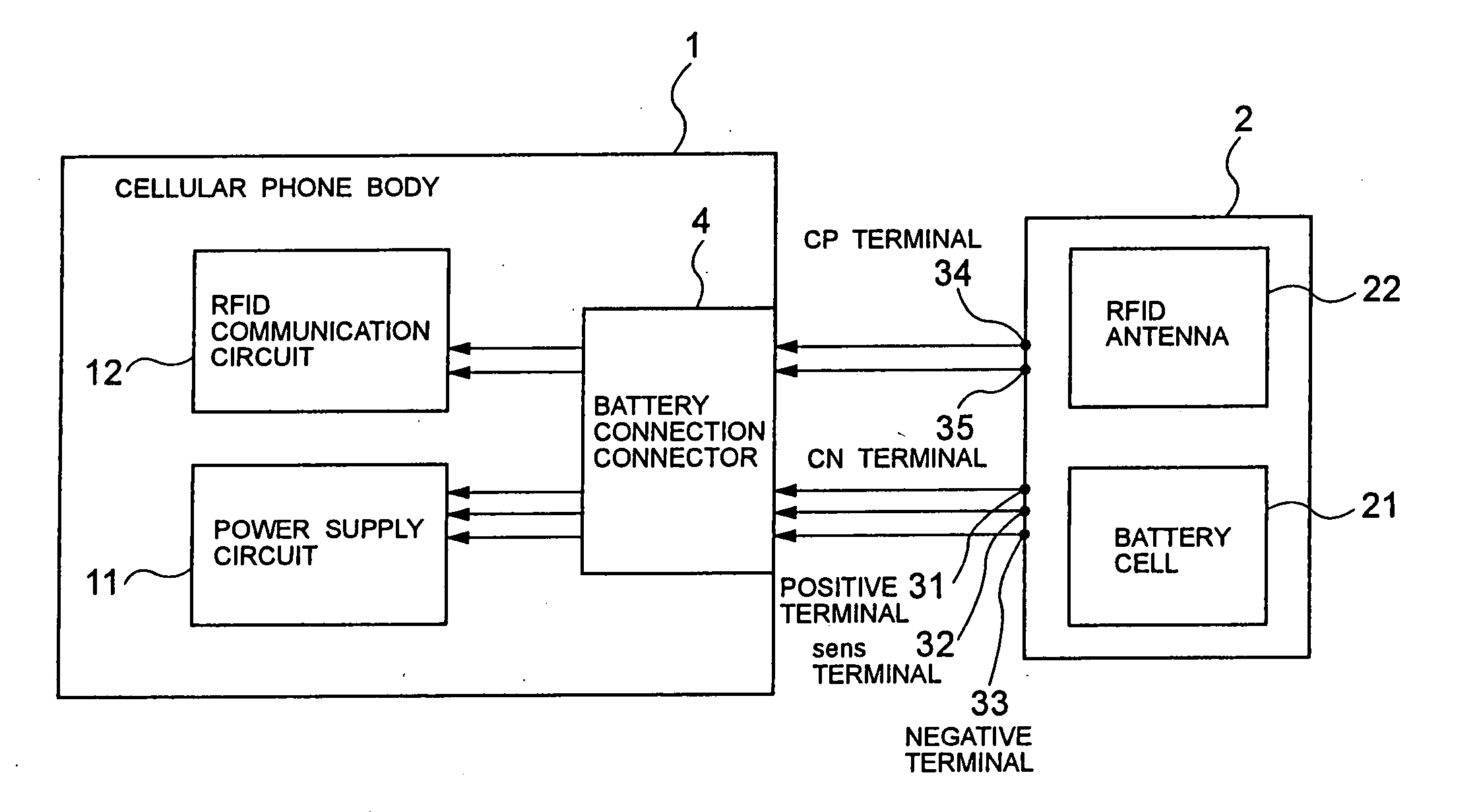
[0033] First, FIG. 7 is a back view of a general cellular phone, in which a back LCD portion 13 and a battery pack 2 are set to the cellular phone body 1 and the battery pack 2 is removably set to the cellular phone body 1 and therefore, a battery connection connector 4 is set to the cellular phone body 1.

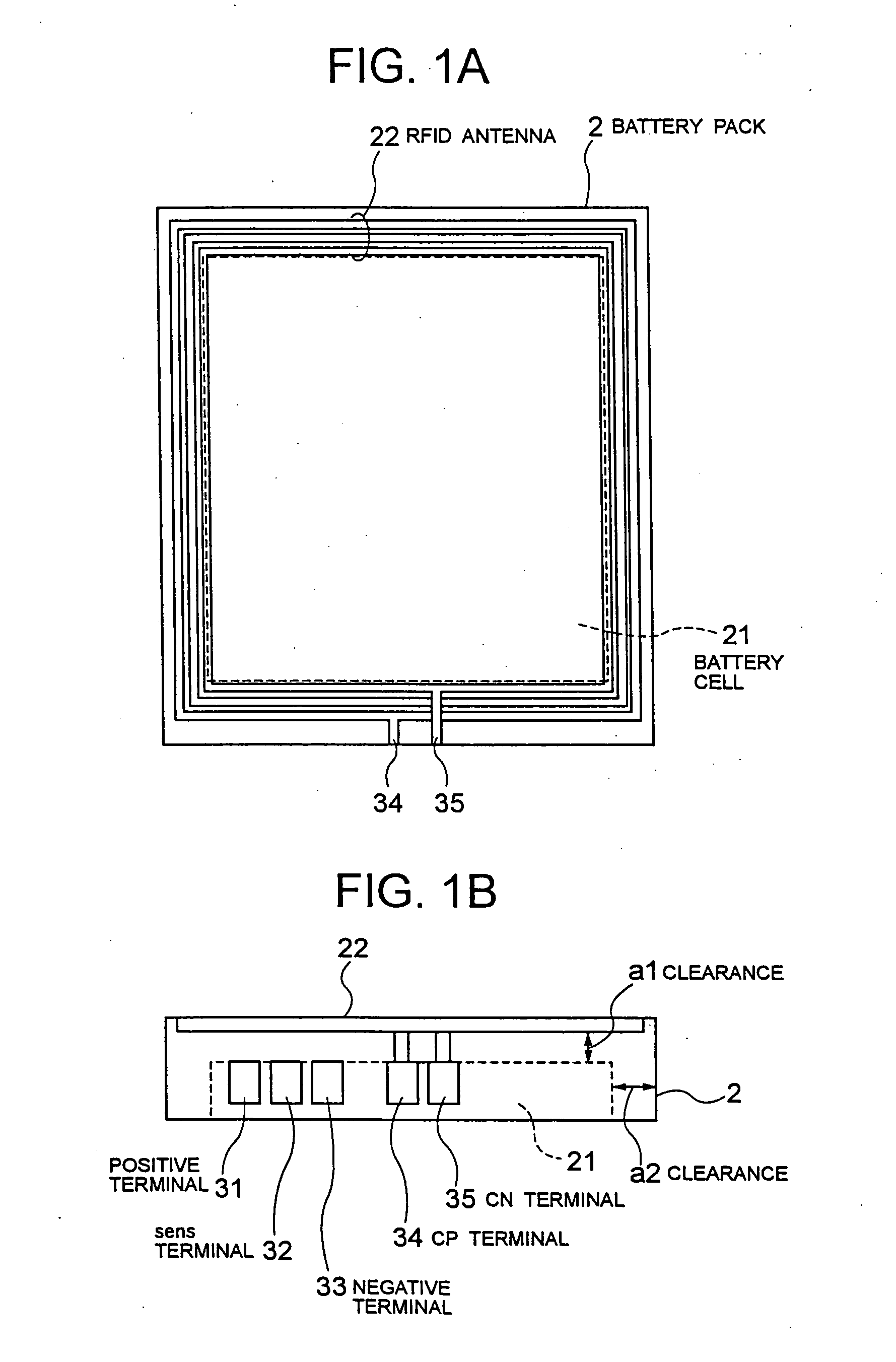
[0034]FIGS. 8A and 8B show a structure of the battery pack 2, in which FIG. 8A is a top view and FIG. 8B is a side view. A battery cell 21 is built in the body of the battery pack 2 and not only a positive terminal 31 and a negative terminal 33 but also a sens terminal 32 are set to the battery cell 21. When mounting the battery pack 2 on the cellular phone body 1 shown in FIG. 7, these terminals 31 to 33 are connected to the battery connection connecto...


PUM


Abstract

The present invention realizes a small thickness and a low price while maintaining the sensitivity of an RFID antenna when setting a non-contact IC card function in a cellular phone. An RFID antenna is mounted on a battery pack of a cellular phone. In this case, by maintaining a predetermined clearance (1 to 2 mm) between the antenna and a battery cell, bad influence of a metallic plate of the battery cell is eliminated. Moreover, in the case of electrical connection with an RFID-function circuit portion, it is unnecessary to prepare a special connector by using a battery connection connector.

Description


Claims


Application Information

Patent Timeline
Owner NEC CORP
Why Eureka
Try Eureka