Electrical connection

a technology of electrical connection and conductive material, which is applied in the direction of conductive materials, non-conductive materials with dispersed conductive materials, conductive materials, etc., can solve the problems of material becoming less pliable and more brittle, and detrimenting the employment of materials over a wide range of potential uses, so as to raise and maintain the temperature of patients

Inactive Publication Date: 2005-12-13
INSPIRATION HEALTHCARE GRP PLC
View PDF14 Cites 72 Cited by
  • Summary
  • Abstract
  • Description
  • Claims
  • Application Information

AI Technical Summary

Benefits of technology

[0010]With the electrical connection installed, the sheet or web can be connected to a suitable power source with the substantial guarantee that there will be no shorting or arcing at the point of electrical connection, or elsewhere along its length and width and consequently no damage by the creating of hot spots.
[0026]The resultant mixture exhibits thixotropic rheological properties, and if required, the viscosity of the mixture can be reduced, by the addition of a suitable solvent such as dimethylformamide.

Problems solved by technology

Whilst electrical heaters at large are generally successful, and more than capable of meeting their intended purpose, what has proved to be difficult, is the achieving of a uniform heating effect over a relatively wide area, substantially free from hot and cold spots or areas.
To attempt to achieve a uniform heating effect, a greater density or concentration of carbon particles is employed, but as a direct result of that, the material becomes less pliable and more brittle, to the detriment of the employment of the material over a wide range of potential uses.

Method used


Image

  • Electrical connection
  • Electrical connection
  • Electrical connection

Examples


Embodiment Construction

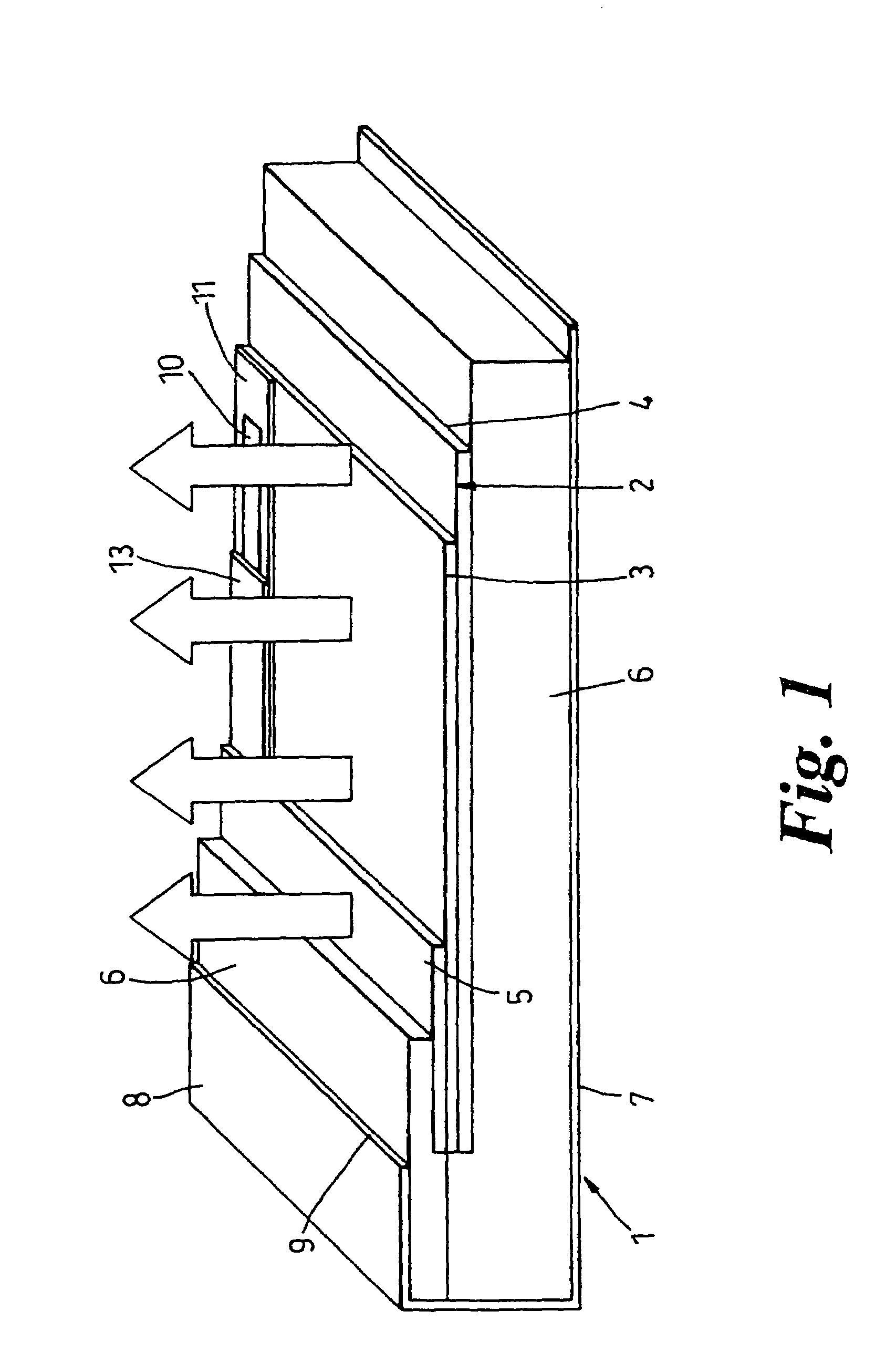
[0047]In FIG. 1, a blanket or mattress 1 has a core 2 formed by conductive material 3 on a fabric support 4. The conductive material was produced by the method hereinbefore defined, and applied to the fabric layer as a series of coatings, with each coating heated to 110° C. to 150° C. by passing through an oven or a series of ovens before the application of a succeeding coating. For medical use, the coating can be 144 microns thick. The conductive material 3 on its fabric support 4 is overlaid by an electrical insulating layer 5, and both encased in a flame retardant insulation 6, of greater thickness to the rear or non-operative side 7 than to the front or operative side 8.

[0048]The whole composite is encased in an outer casing 9 of a polyurethane material, and the edges fully sealed around the full periphery of the blanket or mattress, to ensure that the blanket or mattress is totally waterproof, and readily cleanable and sterilisable.

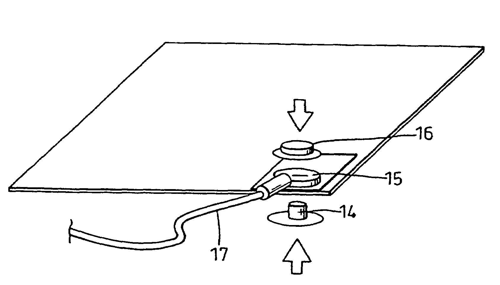
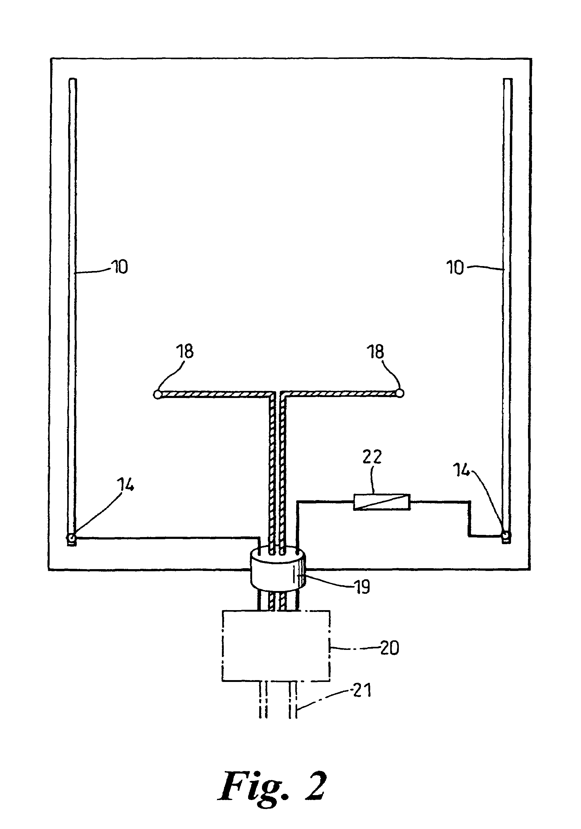
[0049]On the conductive material 3 and below t...


PUM

PropertyMeasurementUnit
thickaaaaaaaaaa
voltageaaaaaaaaaa
timeaaaaaaaaaa

Abstract

A device for connecting a source of electrical power to a coating or film incorporating carbon particles, an objective met by providing a coating of a nickel compound to the coating or film of carbon particles, and applying to the nickel coating a tin-copper tape coated with a silver-loaded conductive adhesive. What results is a uniform heating effect over a relatively wide area, substantially free from hot and cold spots or areas.

Description

RELATED APPLICATION (PRIORITY CLAIM)[0001]This application is a continuation-in-part of U.S. application Ser. No. 09 / 857,241, filed Jun. 1, 2001 now U.S. Pat. No. 6,814,889, which claims the benefit of British application Ser. No. 9826596.0, filed Dec. 4, 1998.BACKGROUND OF THE INVENTION[0002]This invention relates to an electrical connection and is particularly concerned with an electrical connection to conductive materials that can serve the purpose of a heating means.[0003]It has long been known that materials that are electrically conductive can generate heat. This phenomenon has spawned a considerable number of heating means for a considerable number of different purposes.[0004]Whilst electrical heaters at large are generally successful, and more than capable of meeting their intended purpose, what has proved to be difficult, is the achieving of a uniform heating effect over a relatively wide area, substantially free from hot and cold spots or areas.[0005]There have been attemp...

Claims


Application Information

Patent Timeline
Patent Type & Authority Patents(United States)
IPC IPC(8): C08K3/04H01B1/24H05B3/14
CPCC08K3/04H01B1/24H05B3/145H05B3/146
Inventor O'GRADY, PATRICK JAMES
Owner INSPIRATION HEALTHCARE GRP PLC
Why Eureka
Try Eureka