Modular and scalable directional audio array with novel filtering

a directional microphone array, modular technology, applied in the direction of magnetic restriction transducers, transducer details, electrical transducers, etc., can solve the problems of inability to easily scale between small and large configurations for greater effectiveness, significant impact on complexity, noise performance, power consumption, etc., to achieve robust, modular and highly scalable directional microphone arrays, inherently scalable, and sufficient power

Active Publication Date: 2012-07-03
DANIEL TECH
View PDF6 Cites 72 Cited by
  • Summary
  • Abstract
  • Description
  • Claims
  • Application Information

AI Technical Summary

Benefits of technology

[0034]According to one aspect of the invention, a system and method for a robust, modular and highly scalable directional microphone array is provided. The present invention can be quickly assembled into different sizes and configurations which in turn modify the effective pickup pattern of the device. Arrays with few (20 or fewer) to very many (1000 or more) microphones can be constructed with no impact other than being able to support the physical size and weight as well as supplying sufficient power when assembling very large configurations. Beamforming is performed in a distributed fashion—firstly on each module (also known as a “tile” in the preferred embodiment) independently and then, in the case of multiple tiles, secondly on the electrical connection bus. Due to these and associated characteristics, the invention is inherently scalable from small to large sizes with little negative impact on complexity and power requirements—for example, arrays of up to 400 elements can be powered for over 6 hours by a single 9 volt IEC type 6LR61 battery (i.e. a common consumer market 9 volt battery).

Problems solved by technology

Significant problems remain for prior devices to function effectively in the more general case.
Prior devices also can not be easily scaled between small and large configurations for greater effectiveness, without significant impact on complexity, noise performance, power consumption, or architecture.
High-impedance summing circuits inherently have poor noise immunity, which in turn limits the maximum number of microphone elements that can be employed effectively as well as makes them very susceptible to electromagnetic interference.
Prior digital devices are generally complex, even for small systems such as those used in hearing aids.
If many channels are digitized, then they quickly become impacted by the additional size (along with associated weight) and power requirements.
These deficiencies result from the fact that in digital microphone array systems, each microphone channel must be digitized separately and synchronized with all other channels, carried to a central processor for beamforming and other filtering, and then reconverted to analog (sound) for the user to hear.
Therefore, digital implementations suffer from a scaling problem in size, weight, power consumption, and cost as the array size increases to hundreds or thousands of microphones.
As the number of channels increases, the amount of digital noise also increases.
Additional shielding or other techniques are required, which further increase the weight and / or size.
Therefore, any given model digital processor has an inherent limit to how many audio channels it can accommodate.
The limit on the number of audio channels for a given model processor is a significant issue.
This is the limitation inherent in microphone arrays used as hearing aids, for instance—all of the in-ear and on-ear implementations are inherently limited by how much weight, size, and heat can be accommodated by the wearer and therefore, even with sophisticated digital processing, digital hearing aid microphone arrays have limited directionality and sidelobe attenuation.
Prior devices have been constructed from electret or other types of microphones that have excellent sensitivities and do not require the type of phantom power used by studio microphones, but these microphones also have limited ranges of operation over temperature extremes, such as the military might encounter in hot deserts.
However, this array processing section was an all-digital implementation, so it did not take advantage of the microphones' analog electrical properties, nor did it provide for acoustic and vibrational damping, inter-microphone isolation, or wind protection.
Being digital, it still inherently suffered from limitations in scalability regarding power consumption, complexity, heat, and weight.
The scalability limits due to complexity are because of the inherent limits of any given model digital processor and its data bus.
However, employing digital multiplexing in large digital arrays is extremely difficult because of the complexity, cost, power requirements, distance limitations, and timing requirements of the digital circuitry.
Digital multiplexing based implementations are not as versatile since each implementation must be designed for a specific (maximum) size array.
This did reduce the power consumption and complexity of the device compared to all-digital implementations, but the solution created a scalability problem related to noise due to the use of the serial high impedance summing—the more stages, the more noise.
This is not a concern for their targeted application, which was hearing aids, but becomes a limiting issue when scaling up to larger systems to address the general case.
Although this particular implementation was significantly better than previous devices, it also suffered from noise susceptibility to RF interference, summing and other noises, as well as temperature restrictions (due to the electret microphones used).
Previous implementations of analog and digital audio arrays have therefore not been able address all of these concerns simultaneously.

Method used


Image

  • Modular and scalable directional audio array with novel filtering
  • Modular and scalable directional audio array with novel filtering
  • Modular and scalable directional audio array with novel filtering

Examples


embodiment

Preferred Embodiment

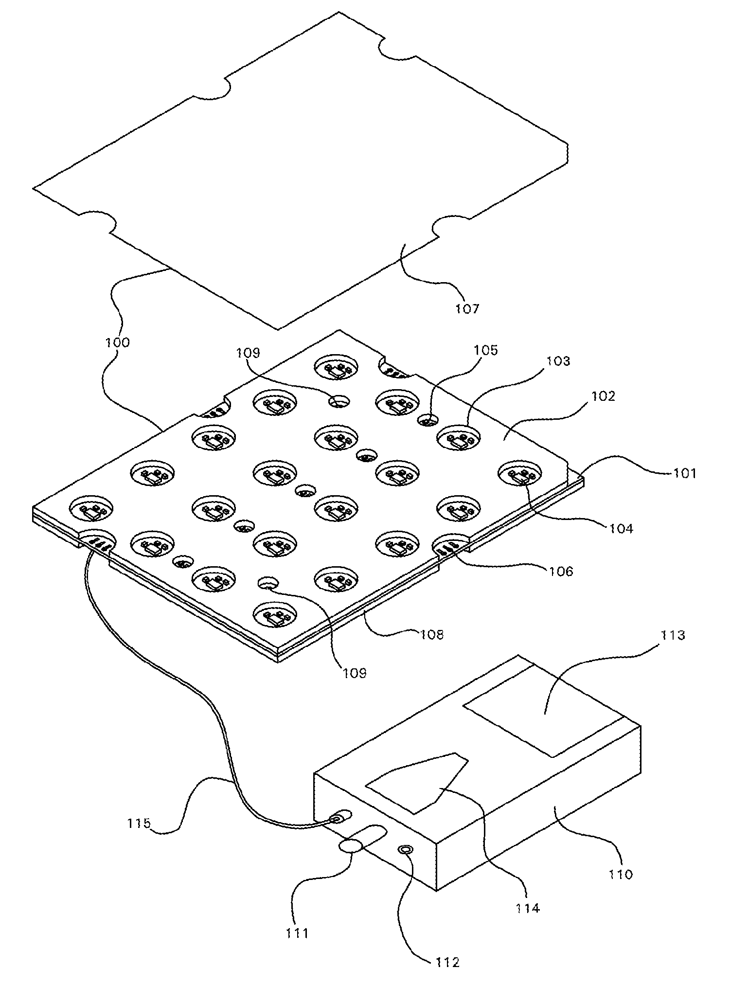
[0082]The manner of using the directional microphone system to listen to remote sound sources is identical to that for parabolic dishes in present use once the system is assembled. The user (listener) simply steers the panel(s) so that the spatial axis that is perpendicular to the plane of the tile(s) is pointed at the targetted sound source. The user then listens through the headphones which are connected to the base unit and makes necessary adjustments to the steering azimuth and elevation so that the desired sound source has the peak response, as determined by listening through the headphones.

[0083]Assembly of the system consists first of connecting the tiles together if there are more than one to be included in the array. Each twenty-element tile in the preferred embodiment has a grid of five microphone elements in one direction and four in the other (of course, this might vary in other embodiments). The user decides upon the arrangement of the tiles in the a...


PUM


Abstract

A directional sensor array system generally for remote audio collection applications that is modular, scalable, and robust with the modules assembled in layers. The invention can alternatively employ sensors other than microphones, such as ultrasonic transducers and accelerometers. In the preferred embodiment, the sensors are mounted on tiles, each of which performs its own local beamforming using a low-impedance resistive summation technique. The tiles are constructed in a layered, sandwiched fashion and incorporate integral protection from wind, sand, dust, moisture, radio frequency noise, vibration, ambient acoustic noise, and directional acoustic noise, as well as provide inter-sensor isolation. Multiple tiles can be joined together physically and electrically. When joined, a secondary parallel beamforming is performed on the bus using electrical summation. Due to the techniques employed, large scale arrays are feasible at low power consumption—for example, an array of 400 microphone elements can be powered for over 6 hours by a single 9 volt battery.

Description

CROSS-REFERENCE TO RELATED APPLICATIONS[0001]The present application is a continuation of U.S. patent application Ser. No. 11 / 462,978, filed Aug. 7, 2006 now abandoned, and the content of which is incorporated herein by reference.FIELD OF THE INVENTION[0002]The present invention generally relates to directional audio systems and in particular to the design, construction and processing (i.e. filtering and rendering) of robust, modular, and scalable directional audio systems.BACKGROUND OF THE INVENTION[0003]General governmental, as well as consumer, applications for remote audio collection require operation in many different, challenging environments such as indoor, outdoor, automobile and portable (body-carried or -worn), which experience a variety of bothersome conditions, such as wind, sand, dust, precipitation, radio frequency (RF) interference (e.g. from mobile communications), extreme temperatures, and acoustic noises. Limited scenarios have been addressed by prior devices, such...

Claims


Application Information

Patent Timeline
Patent Type & Authority Patents(United States)
IPC IPC(8): H04R15/00
CPCH04R3/005H04R2201/401
Inventor DANIEL, THOMAS MARTIN
Owner DANIEL TECH
Why Eureka
Try Eureka