Blanking mould
A punching die and base material technology, applied in the field of punching dies with high punching precision, can solve problems such as maintaining the levelness of the blade, and achieve the effect of eliminating deflection and high punching precision
- Summary
- Abstract
- Description
- Claims
- Application Information
AI Technical Summary
Problems solved by technology
Method used
Image

Examples
Embodiment 1
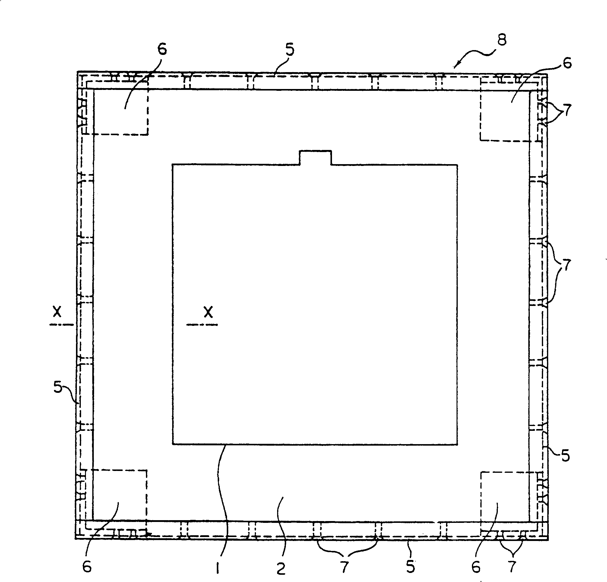
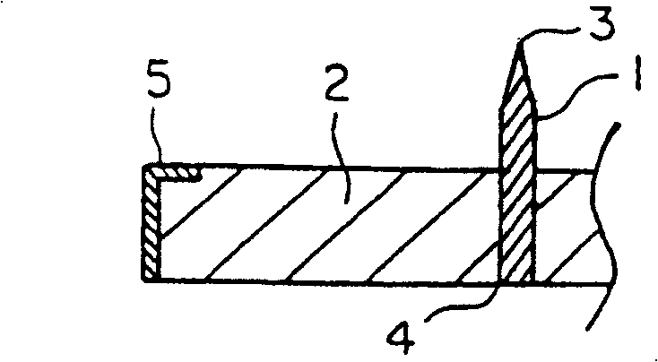
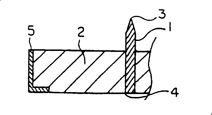
[0037] Fig. 1 (a) is the top view of an embodiment of the blanking die of the present invention, the blanking of the cutting blade 1 with a height of 23.6mm is placed in the narrow groove of the square base material 2 (plywood plywood with a thickness of 18mm) In the mold 8, the side faces of the four sides of the base material 2 are reinforced by four L-shaped angle irons 5 . The L-shaped angle irons 5 are fixed in a state connected at right angles using corner members 6 having right-angled side surfaces at the corners. Screws 7 are used to fix the L-shaped angle iron 5 to the base material 2 and the corner member 6 . Fig. 1(b) is a cross-sectional view along line X and X in Fig. 1(a). L word angle iron also can use in reverse as Fig. 1 (c).
[0038]The shape seen from the outside and the inside of the corner member 6 is shown in a perspective view in FIG. 2( a ) and FIG. 2( b ). Figure 3(a) ~ Figure 3(c) It is a perspective view illustrating the exploded structure of the...
Embodiment 2
[0041] FIG. 4( a ) is a plan view of another embodiment of a component that changes the corner component 6 into the shape shown in the perspective view of FIG. 4( b ). and Figure 1(a) ~ Figure 1(c) The same symbols mean the same components. The base material 2 of the blanking die shown in Fig. 4(a) is also cut into the shape of an angle iron 5 and a corner part 6 as shown in Fig. 3(a), and each part is placed on it and fixed by a screw. 7 fixed.
Embodiment 3
[0043] In Fig. 5 (a) it is shown that the F-shaped bar 5' (made of steel) is used to replace Figure 1(a) ~ Figure 1(c) Partial cut-away perspective view of the L-shaped angle iron 5 in . Like the L-shaped angle iron 5, the F-shaped bar 5' can also be used up and down.
[0044] In addition, Fig. 5(b) shows a partial cross-sectional perspective view when using the 匚-shaped angle iron 5". For the 匚-shaped angle iron 5", it can also be used up and down in reverse with that of Fig. 5(b), and the parenthesis can also be used The upper and lower sides and sides of the material 2 are used for reinforcement.
PUM
 Abstract
Description
Claims
Application Information
 - R&D
- Intellectual Property
- Life Sciences
- Materials
- Tech Scout
- Unparalleled Data Quality
- Higher Quality Content
- 60% Fewer Hallucinations
Browse by: Latest US Patents, China's latest patents, Technical Efficacy Thesaurus, Application Domain, Technology Topic, Popular Technical Reports.
© 2025 PatSnap. All rights reserved.Legal|Privacy policy|Modern Slavery Act Transparency Statement|Sitemap|About US| Contact US: help@patsnap.com