Panel device for railway rolling stock

A railway vehicle and vehicle connection technology, applied in the direction of railway car body, railway car body parts, transportation and packaging, etc., can solve the problems of complex structure and many sliding parts, and achieve the effect of excellent structure, improved appearance and improved safety

Inactive Publication Date: 2008-08-27
NARITA SEISAKUSHO
View PDF5 Cites 0 Cited by
  • Summary
  • Abstract
  • Description
  • Claims
  • Application Information

AI Technical Summary

Problems solved by technology

[0008] However, in this method, there are many sliding parts between members and the structure is complicated, and there are problems in maintenance and management.

Method used


Image

  • Panel device for railway rolling stock
  • Panel device for railway rolling stock
  • Panel device for railway rolling stock

Examples


Embodiment Construction

[0043] The best mode for carrying out the present invention will be described below with reference to the embodiments shown in the drawings.

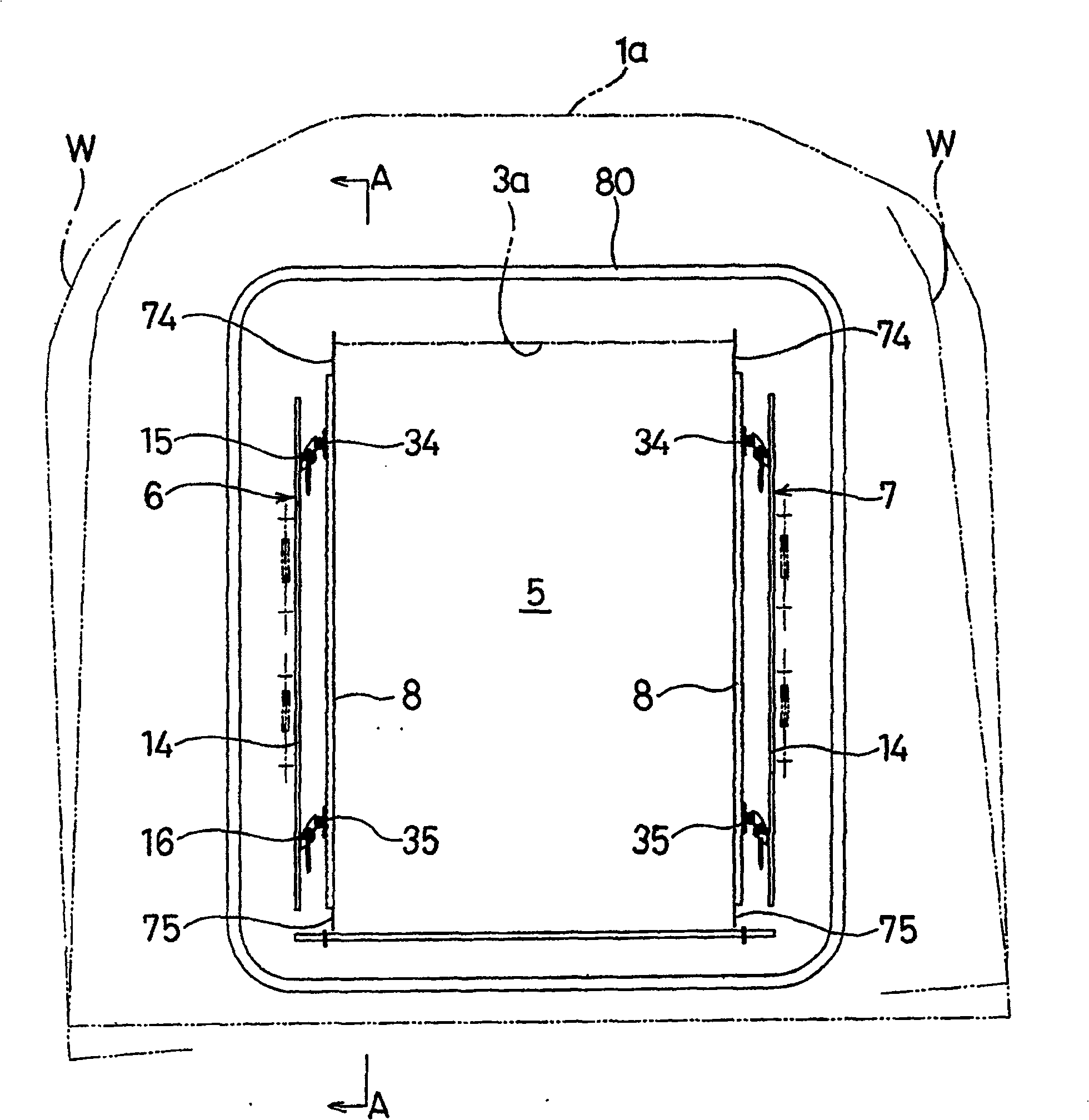
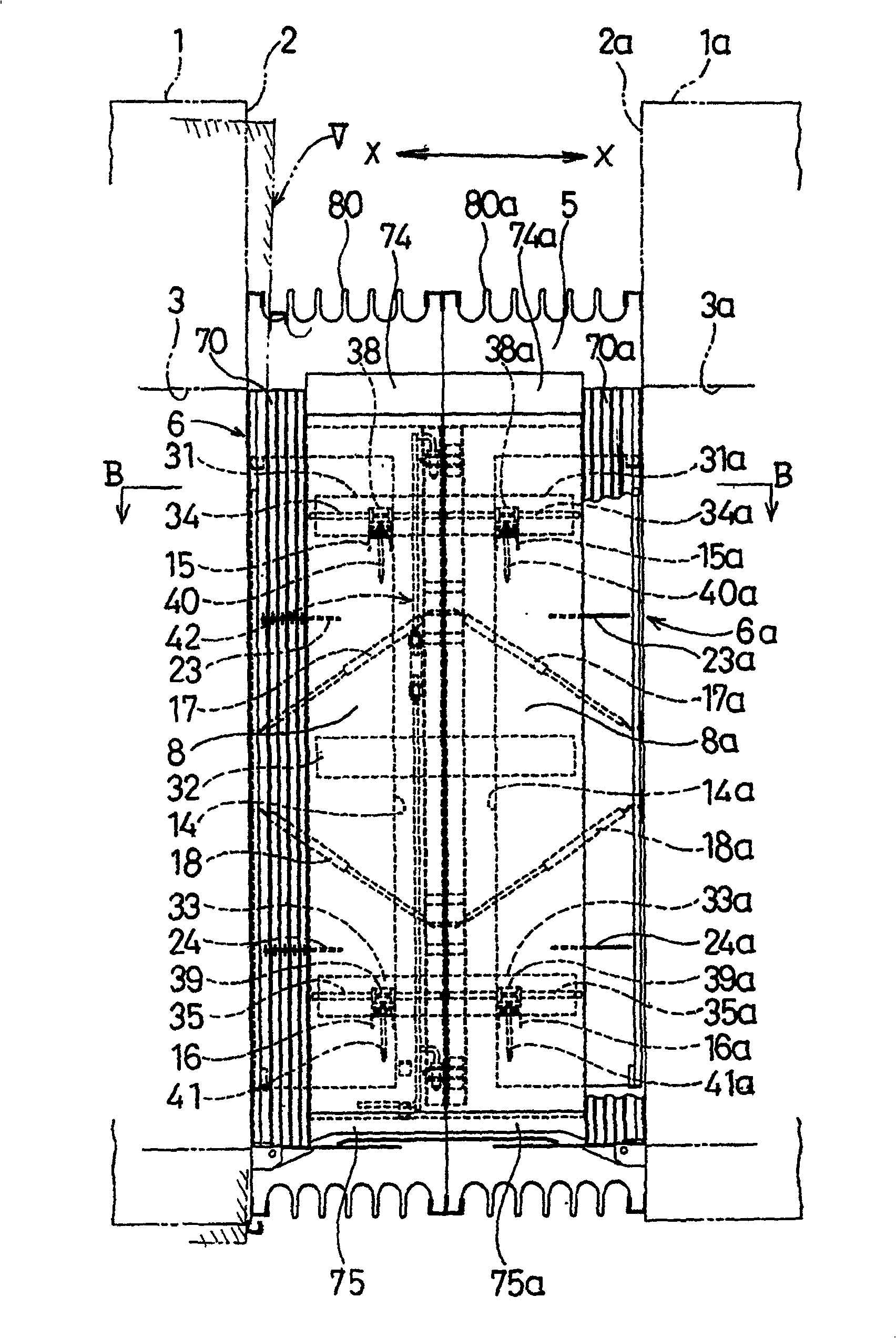
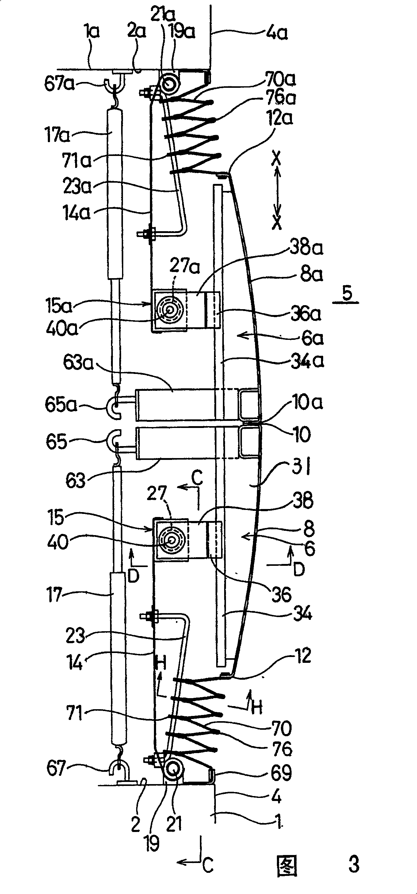
[0044] figure 1 The figure obtained by looking at the connecting surface of the vehicle from the middle of the connecting part of the vehicle, figure 2 yes means figure 1 The cross-sectional view of line A-A in Figure 3 is a representation of the figure 2 An enlarged cross-sectional view of line B-B in .

[0045] In these figures, since equivalent members are respectively provided on the two connected vehicles, the same members as the members on one side of vehicle 1, that is, the members on the other side of vehicle 1a, may be added to one side as necessary. Members on the vehicle side are indicated by adding a to the symbols, and descriptions thereof are omitted to avoid cumbersome descriptions.

[0046] figure 1 and figure 2 Among them, the left and right sides of the connecting channel 5 between the connecting surfaces 2, 2...


PUM


Abstract

On a side portion of an interconnection passage (5), a supporting panel (14, 14a) provided on each of coupled cars (1, 1a), so as to be horizontally rotatable with a center of rotation (21, 21a) being on a car end face (2, 2a) side; a vertical bearing (27, 27a) provided on an end portion of the supporting panel (14, 14a); a side panel (8, 8a) provided on an interconnection passage (5) side of the supporting panel; a rail (34, 34a) provided horizontally on the side panel; a slider (36, 36a) provided slideably on the rail; a guide shaft (40, 40a) provided vertically on the slider and inserted slideably in the bearing; an extensible sheet (70, 70a) stretched between the side panel and a car end face; and a balancer (17, 17a) extended between the side panel and the car end face to hang the side panel in the middle in a passage direction. In order that a passenger can not open the panel by his or her hand by a constitution in which the structure is simple and the maintenance operation management is easy.

Description

technical field [0001] The invention relates to a plate arrangement for a railway vehicle. Background technique [0002] Conventionally, various side walls have been proposed for the safety of the passers-by and the design of the passage for the side of the passageway of the railway vehicle joint, that is, the passageway. [0003] Among such side walls, there has been a conventional one that can rotate the movable plate in the horizontal direction and attach it to the connecting surface (Japanese: wife surface) of the vehicle, protrude from the connecting surface, and use a spring to close the plate and keep it in a normal state. Proposal (refer to JP-Y2-3-26048). [0004] In this prior art, there is a problem that the passenger opens the panel against the closing force of the spring with his hand and can put his hand in the panel. [0005] As a method for solving this problem, there is known a method of providing a rope for preventing the panel from opening on the movable...

Claims


Application Information

Patent Timeline
Patent Type & Authority Patents(China)
IPC IPC(8): B61D17/20
CPCB61D17/20
Inventor 波多野干夫
Owner NARITA SEISAKUSHO
Why Eureka
Try Eureka