Wiper blade

A technology of wiper blades and wipers, which is applied in vehicle maintenance, coating, special surfaces, etc., can solve the problems of high cost, high dry friction coefficient, etc., and achieve the effect of low noise

Inactive Publication Date: 2008-09-17
ROBERT BOSCH GMBH
View PDF4 Cites 2 Cited by
  • Summary
  • Abstract
  • Description
  • Claims
  • Application Information

AI Technical Summary

Problems solved by technology

[0003] A disadvantage of the wiper strips or wiper lips of known wipers is that they have a high dry friction coefficient μ when operating on conventional windshields tr
[0004] This dry coefficient of friction is between 0.8 and 1.2, which is greater than the coefficient of friction occurring in the case of a wet windshield, which requires a powerful and therefore expensive wiper drive

Method used


Image

  • Wiper blade
  • Wiper blade
  • Wiper blade

Examples


Embodiment Construction

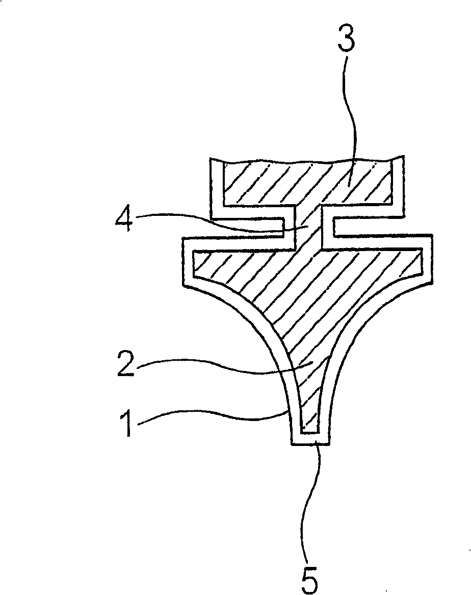
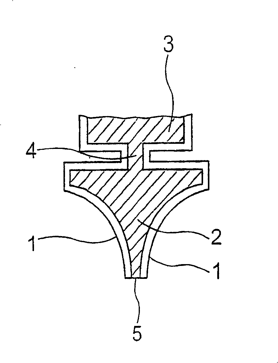
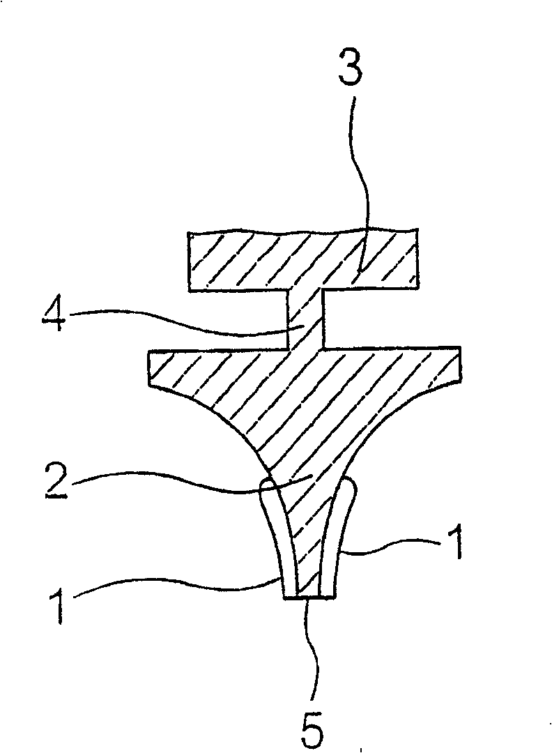
[0029] exist figure 1 shows a wiper blade consisting of a wiper lip 2 made of rubber material and having a wiper edge (Wischkante ) 5; the head part 3 is only partially shown here and is made of rubber material; the switching strip 4 is made of rubber material and is arranged between the head part 3 and the wiper lip 2 .

[0030] The wiper lip 2, the head part 3 and the switching strip 4 are provided with a surface which consists of a layer of polyethylene 1, which is shown in the figure 1 In the middle, the wiper lip 2 , the head part 3 and the switch strip 4 are shown enlarged compared to the wiper lip 2 . The polyethylene layer 1 is currently made of PE-UHMW, that is to say of polyethylene with an ultra-high molar mass.

[0031] according to figure 1 The wiper blades are produced by first extruding partially vulcanized rubber material in an extruder with the aid of a tool in a wiper blade mold, then sprinkled with PE-UHMW powder and subsequently vulcanized. The conditio...


PUM

PropertyMeasurementUnit
friction coefficientaaaaaaaaaa

Abstract

A wiper blade for a windshield wiper, in particular for a windshield wiper of a motor vehicle, is proposed, which has a wiper blade rubber with a wiper blade rubber lip (2). In order to achieve a low dry friction coefficient, the wiper blade rubber lip (2) is fabricated partially of polyethylene.

Description

technical field [0001] The invention relates to a wiper blade for a windshield wiper, in particular for a motor vehicle windshield, which has a wiper rubber strip with a wiper lip. Background technique [0002] Wiper blades of the aforementioned type are known from practice and comprise a wiper strip formed with a wiper lip. The wiper strip or wiper lip is made of a rubber material which is produced, for example, on the basis of natural rubber. [0003] A disadvantage of the wiper strips or wiper lips of known wipers is that they have a high dry friction coefficient μ when operating on conventional windshields tr . [0004] This dry coefficient of friction is between 0.8 and 1.2, which is greater than the coefficient of friction occurring in the case of a wet windshield, which would require a powerful and therefore expensive wiper drive. Contents of the invention [0005] A wiper blade according to the invention for a windshield wiper, in particular for a vehicle windsh...

Claims


Application Information

Patent Timeline
Patent Type & Authority Patents(China)
IPC IPC(8): B60S1/38B05D1/06B05D1/24B05D1/26B05D3/02B05D7/02C08J7/046
CPCB05D1/265B05D3/0254B05D1/24B05D5/00C08J7/047B05D5/08C08J2423/00B60S1/38B60S2001/3829B05D1/06C08J2321/00B05D7/02Y10T428/31909C08J7/0427C08J7/046
Inventor A·沃格特L·米勒U·哈森科克斯G·克拉姆特W·迪尔克斯
Owner ROBERT BOSCH GMBH
Why Eureka
Try Eureka