Supercharge Your Innovation With Domain-Expert AI Agents!

Detection apparatus for girdle bounce of valve of air cylinder cover

A cylinder head and valve technology, applied in the direction of angle/taper measurement, etc., can solve the problems of limited production efficiency, inconvenient movement, inconvenient detection, etc., and achieve the effect of improving production efficiency, easy to move, and convenient to detect.

Active Publication Date: 2008-09-17
ZHEJIANG GEELY AUTOMOBILE RES INST CO LTD +1
View PDF5 Cites 0 Cited by
  • Summary
  • Abstract
  • Description
  • Claims
  • Application Information

AI Technical Summary

Problems solved by technology

[0003] The purpose of the present invention is to provide a light weight, easy to move, convenient to detect, which is beneficial to improve production efficiency, and solves the inconvenience of moving, inconvenient detection and large limitations of the existing detection instruments. , limiting production efficiency and other issues

Method used


Image

  • Detection apparatus for girdle bounce of valve of air cylinder cover
  • Detection apparatus for girdle bounce of valve of air cylinder cover
  • Detection apparatus for girdle bounce of valve of air cylinder cover

Examples


Embodiment 1

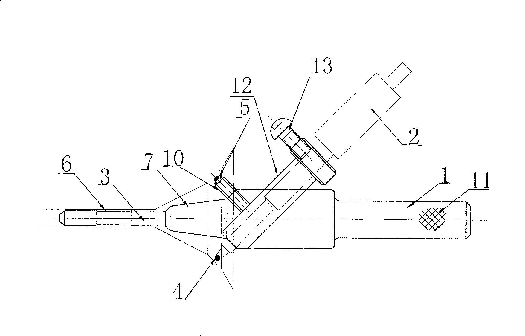
[0018] Embodiment 1: as figure 1 As shown, the inspection tool includes a inspection body 1 and a dial indicator 2. The outer surface of the inspection body 1 is provided with a grid-shaped groove 11. The front end of the inspection body 1 is provided with a cylinder 3 matching the valve guide. The cylinder 3 is provided with An annular groove 6 coaxial with the cylinder 3 . A transition section 7 is provided between the inspection body 1 and the cylinder 3, and the transition section 7 is in a conical structure, the small end of which is connected to the cylinder 3, and the large end is connected to the inspection body 1. The positioning steel ball 5 is arranged at the end of the sleeve 10, the sleeve 10 and the axis of the cylinder form an angle of 45°, the positioning steel ball 5 and the end of the dial indicator contact 4 are roughly located on the same circle, and the center of the circle is extended on the axis of the cylinder Wire.

[0019] The middle section of the ...

Embodiment 2

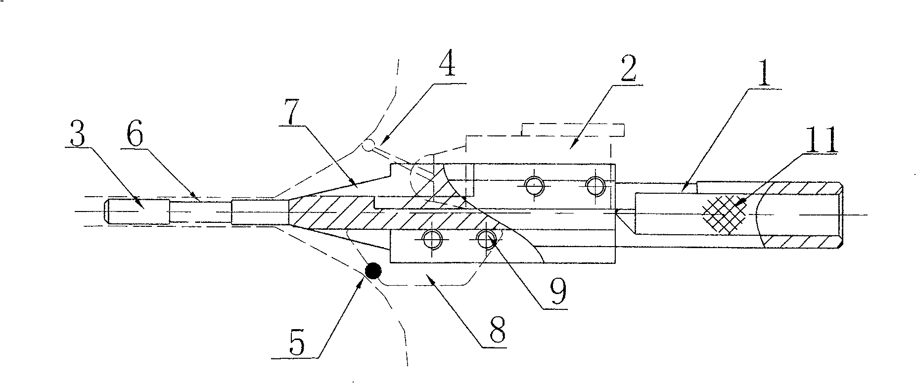
[0022] Embodiment 2: as image 3 As shown, the inspection tool includes a inspection body 1 and a dial indicator 2. The outer surface of the inspection body 1 is provided with a grid-shaped groove 11. The front end of the inspection body 1 is provided with a cylinder 3 matching the valve guide. The cylinder 3 is provided with An annular groove 6 coaxial with the cylinder 3 . A transition section 7 is provided between the inspection body 1 and the cylinder 3, and the transition section 7 is in a conical structure, the small end of which is connected to the cylinder 3, and the large end is connected to the inspection body 1. The positioning steel ball 5 is arranged on the sliding positioning block 8, and the sliding positioning block 8 is slidingly connected with the inspection body 1 and positioned by the positioning screw 9. The axis of the connecting rod and the front end cylinder 3 form 45°, the positioning steel ball 5 and the end of the dial indicator contact 4 are roughl...


PUM


Abstract

The invention of the valve girdle jumpiness detection utensil for the engine cylinder cap belongs to the technology area of the detection utensil in process of the automobile production. It comprises the body of the detection utensil and the dial indicator. A column which matches with the valve guide bushing is mounted at the front of said detection utensil, said dial indicator is approximately set at the middle of the detection utensil and its contactor staggers with the axial of the column, the free rotational locating steel balls are mounted on the detection utensil, and they are in the same circle with the end part of the dial indicator contactor, the center of said circle is at the extended line of the column axial. The invention is light in weight, easy to move, convenient to detect, furthersome to improve the production efficiency. It resolves the current problems of detecting instrument which is difficult to move, inconvenient to detect, big limitation, restraining the production efficiency.

Description

technical field [0001] The invention relates to an engine cylinder head valve ring belt runout inspection tool, which belongs to the technical field of inspection instruments in the engine production process. Background technique [0002] In the prior art, to detect the valve annulus of the engine cylinder head, that is, the jump between the valve guide and the 90° cone surface of the seat ring, the cylinder head needs to be fixed on a special detection instrument, and the volume of this instrument is large and inconvenient to move, so The detection of the cylinder head valve ring belt can only be carried out in a special detection place, which is inconvenient and limited, which limits the production efficiency. Contents of the invention [0003] The object of the present invention is to provide a light weight, easy to move, convenient to detect, and beneficial to improve production efficiency cylinder head valve ring beating inspection tool, which solves the inconvenience...

Claims


Application Information

Patent Timeline
Patent Type & Authority Patents(China)
IPC IPC(8): G01B5/25
Inventor 李书福夏金海
Owner ZHEJIANG GEELY AUTOMOBILE RES INST CO LTD
Features
  • R&D
  • Intellectual Property
  • Life Sciences
  • Materials
  • Tech Scout
  • Unparalleled Data Quality
  • Higher Quality Content
  • 60% Fewer Hallucinations
Learn More