Vertical cylinder-installing and cap-mounting machine

A cylinder and cap machine technology, applied in metal processing, metal processing equipment, manufacturing tools, etc., can solve the problems of damage to the seal and thread surface, uneven gap between the guide sleeve and the hydraulic cylinder, oil leakage, etc., to achieve the elimination of hydraulic pressure The effect of cylinder mouth slip

Active Publication Date: 2008-10-22
郑州煤机特种锻压制造有限公司
View PDF4 Cites 0 Cited by
  • Summary
  • Abstract
  • Description
  • Claims
  • Application Information

AI Technical Summary

Problems solved by technology

The shortcomings of this disassembly method are mainly manifested in the fact that the piston rod of the hydraulic column or jack sags due to its own weight, resulting in an uneven gap between the guide sleeve and the hydraulic cylinder, which is located between the guide sleeve and the lower peripheral surface of the hydraulic cylinder. There is no assembly gap to damage the sealing and threaded surface, so that the oil leakage after the guide sleeve and the hydraulic cylinder are assembled

Method used


Image

  • Vertical cylinder-installing and cap-mounting machine

Examples


Embodiment Construction

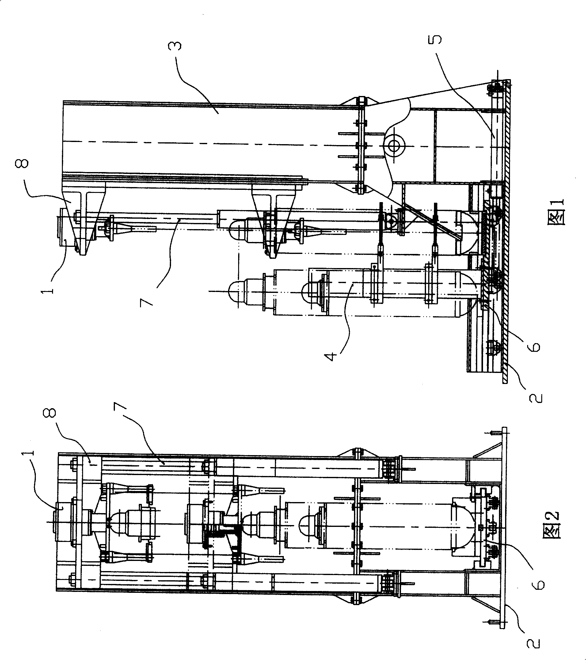
[0010] As shown in the figure, the vertical cylinder capping machine of the present invention includes a frame of an "L" shape formed by a base 2 and a vertical beam 3 vertically arranged thereon, and a capping drive device 1, The horizontal guide rail on the base 2 and the vertical guide rail on the vertical beam 3; the base 2 is provided with a fixed pile 4; the horizontal guide rail is provided with a loading vehicle 6 driven by a horizontal hydraulic jack 5; A slide block 8 driven by a vertical hydraulic jack 7 is arranged on the vertical guide rail, and the upper cap driving device 1 is arranged on the slide block 8 .

[0011] The working principle of the present invention is as follows:

[0012] When the guide sleeve needs to be disassembled, the hydraulic column or jack is vertically hoisted on the loading vehicle 6 by driving or other tools, and the loading vehicle 6 is driven by the horizontal hydraulic jack 5 to move the hydraulic column or jack to the upper cap driv...


PUM


Abstract

The vertical cylinder installing and cap mounting machine includes one frame and one cap driving mechanism. The frame consists of pedestal, column on the pedestal, horizontal track on the pedestal and vertical track on the column, fixed stake on the pedestal, loading bogie driven with horizontal hydraulic jack and set on the horizontal track, and sliding block driven with vertical hydraulic jack and set on the vertical track. The cap driving mechanism is set on the sliding block. The present invention has the advantages of homogeneous interval between the guide sleeve and the cylinder barrel during assembling, greatly raised assembling precision and long service life.

Description

technical field [0001] The invention relates to installation and disassembly equipment, in particular to a vertical cylinder loading and capping machine. Background technique [0002] In the assembly process of heavy-duty hydraulic columns and jacks, when installing or dismounting the threaded guide sleeve on the hydraulic cylinder, it is often used to place the hydraulic cylinder horizontally and then use the upper cap driving device to mount or remove the guide sleeve. The shortcomings of this disassembly method are mainly manifested in the fact that the piston rod of the hydraulic column or jack sags due to its own weight, resulting in an uneven gap between the guide sleeve and the hydraulic cylinder, which is located between the guide sleeve and the lower peripheral surface of the hydraulic cylinder. There is no assembly clearance to damage the sealing and threaded surface, so that oil leakage occurs after the guide sleeve and hydraulic cylinder are assembled. Contents...

Claims


Application Information

Patent Timeline
Patent Type & Authority Patents(China)
IPC IPC(8): B23P19/04
Inventor 高有进徐宗林徐良谢永春顾建平周志刚刘文林
Owner 郑州煤机特种锻压制造有限公司
Why Eureka
Try Eureka