
Friction clutch, particularly for a motor vehicle, comprising differentiated friction means

一种摩擦离合器、离合器的技术,应用在摩擦离合器、机械驱动离合器、离合器等方向,能够解决托板脆弱等问题

Active Publication Date: 2008-12-10
VALEO EMBRAYAGES SAS
View PDF7 Cites 0 Cited by
  • Summary
  • Abstract
  • Description
  • Claims
  • Application Information

AI Technical Summary

Problems solved by technology

[0016] [16] However, the joint cut constitutes a material defect that makes the pallet weak

Method used


Image

  • Friction clutch, particularly for a motor vehicle, comprising differentiated friction means
  • Friction clutch, particularly for a motor vehicle, comprising differentiated friction means
  • Friction clutch, particularly for a motor vehicle, comprising differentiated friction means

Examples


Embodiment Construction

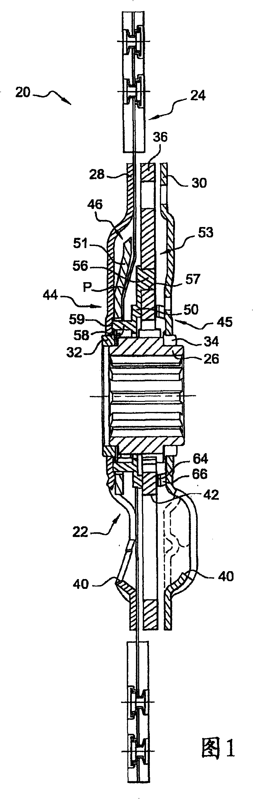
[0053] [53] FIG. 1 shows a friction device of a friction clutch according to a first embodiment of the present invention.

[0054] [54] In the example described, the clutch is used on a motor vehicle to couple a driven shaft, such as the input shaft of a gearbox, with a driven shaft, such as the crankshaft of an internal combustion engine.

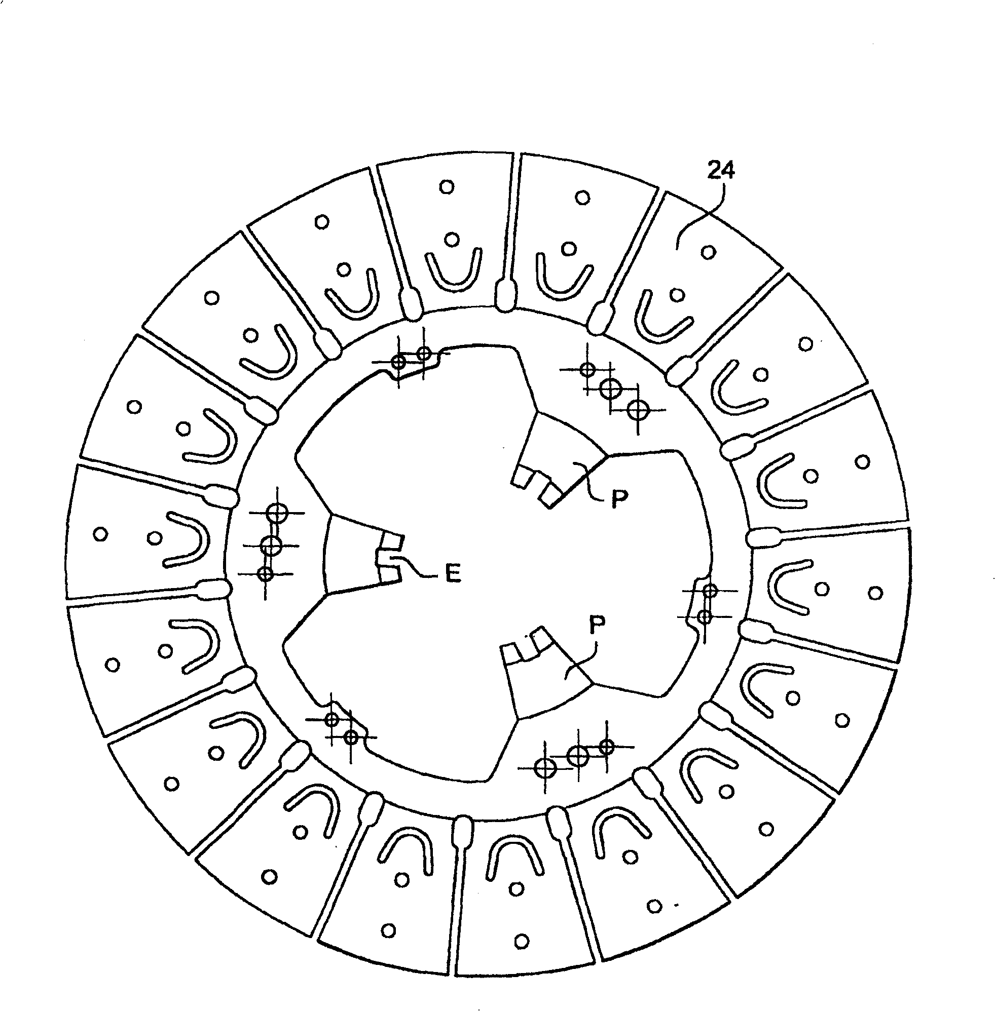
[0055][55] The friction device, generally indicated by the reference numeral 20, has damping means comprising a damper 22. The shock absorber 22 is installed between a rotary input part such as a friction plate 24 and a rotary output part such as a cylindrical bushing 26 coupled to the driven shaft through a longitudinal inner groove provided in the bushing. The input and output parts are substantially coaxial.

[0056] [56] The friction plate 24 is clamped in a known manner between a power flywheel rotatably connected to the drive shaft and a pressure plate driven by the clutch element.

[0057] [57] The shock absorber includes a first ...


PUM


Abstract

The invention relates to a clutch comprising at least one shock absorber (22), comprising: a rotating input part (24) and a rotating output part (26); a first guiding washer (28) and a second guiding washer (30) ) carrying a circumferentially acting elastic member, the first and second guide washers are rotationally connected to one of the input part (24) and the output part (26), and are connected to the input part (24) and the output part ( 26) in another rotary connection. The clutch additionally includes a friction member (44) driven by the relative angular displacement of the guide washers (28, 30) and the carrier plate (36), the friction member comprising a friction member capable of coupling with the carrier plate (36) via complementary circumferential stops. A component (46), wherein the coupling stops are several pairs, and the coupling stops cooperate with each other only when the supporting plate (36) is angularly displaced relative to the guide washers (28, 30) in a predetermined direction. Complementary circumferential stops are provided on the friction member (46) and on a member (50) distinct from the carrier plate (36) and the friction member (46), member (50) being rotatably connected to the carrier plate (36).

Description

technical field [0001] [01] The present invention relates to a friction clutch, in particular for a motor vehicle, comprising different friction components. Background technique [0002] [02] In a motor vehicle, the function of a friction clutch is to transmit torque between a rotating input member and a rotating output member through frictional clamping between a pressure plate and a powered flywheel. [0003] [03] The input part is generally formed by a friction plate, while the output part is formed by a bushing for coupling with the input shaft of the gearbox. [0004] [04] The role of the friction clutch is also to ensure the continuity of the transmitted torque, and to filter the shock from the engine, especially through the damping part including the elastic member and the friction part. [0005] [05] When the power flywheel is coupled with the input shaft of the gearbox through the friction clutch, the input shaft of the gearbox generally bears a torque along the fi...

Claims


Application Information

Patent Timeline
Patent Type & Authority Patents(China)
IPC IPC(8): F16D13/64F16F15/123F16F15/129
CPCF16D13/644F16F15/1238F16F15/129
Inventor L·拉马纳P·鲁雄
Owner VALEO EMBRAYAGES SAS
Features
  • Generate Ideas
  • Intellectual Property
  • Life Sciences
  • Materials
  • Tech Scout
  • Unparalleled Data Quality
  • Higher Quality Content
  • 60% Fewer Hallucinations
Learn More