
Stubble-plow type tilling machine for plowing ground

A technology for tillers and disc harrows, applied in the directions of harrows, agricultural machinery and implements, applications, etc., can solve problems such as inability to remove the discs

Inactive Publication Date: 2008-12-24
米歇尔·埃文
View PDF6 Cites 1 Cited by
  • Summary
  • Abstract
  • Description
  • Claims
  • Application Information

AI Technical Summary

Problems solved by technology

Also, with this machine it is not possible to remove every disc

Method used


Image

  • Stubble-plow type tilling machine for plowing ground
  • Stubble-plow type tilling machine for plowing ground
  • Stubble-plow type tilling machine for plowing ground

Examples


Embodiment Construction

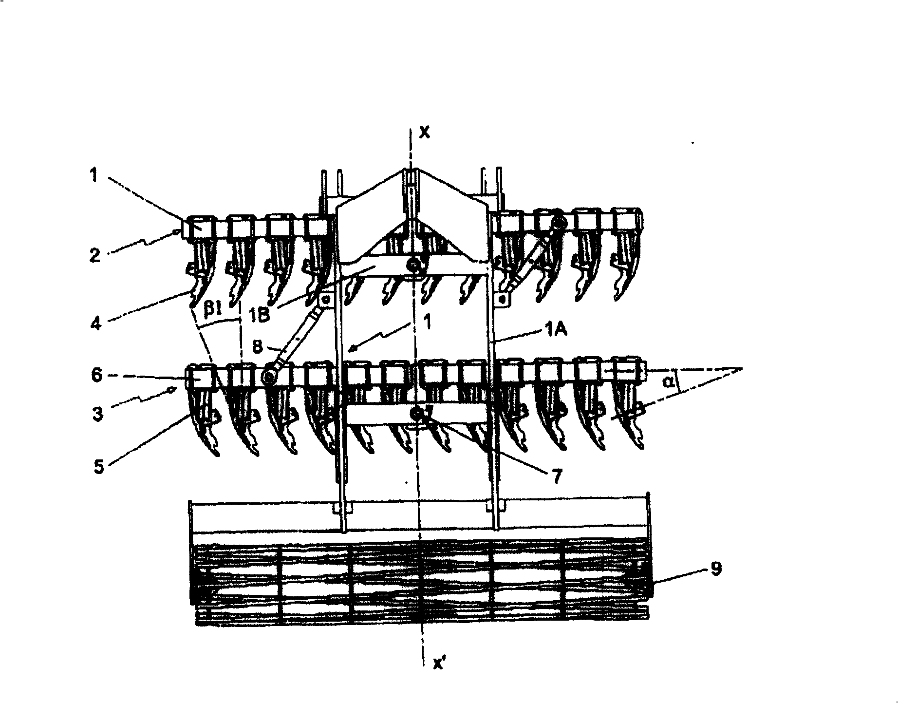
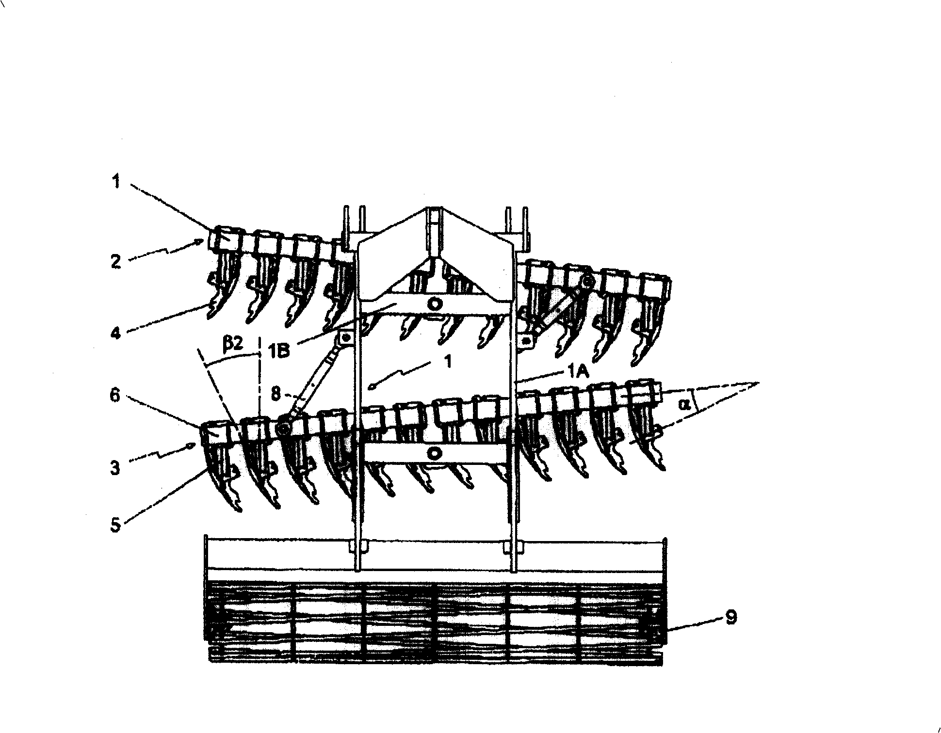
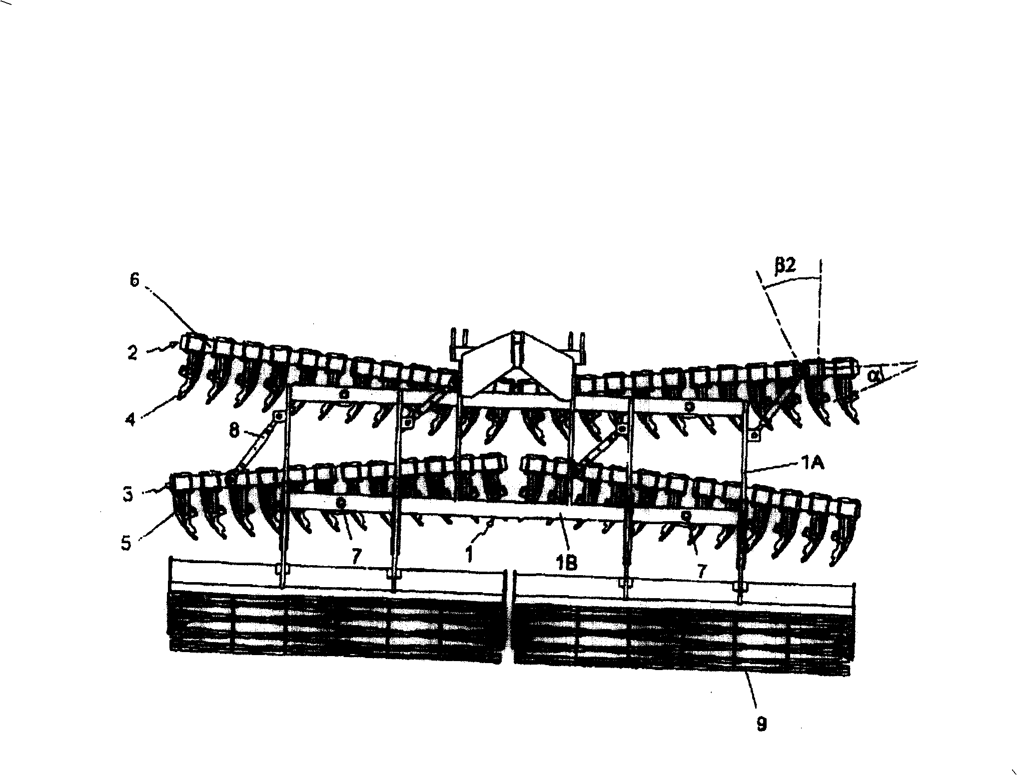
[0016] As mentioned above, the precision disc harrow type soil tillage machine according to the present invention comprises a suspended or trailed chassis 1 provided with tillage implements, which can have a large number of forms. In the examples shown, this chassis 1 is constituted by at least one frame formed by two bars 1A interconnected by a cross bar 1B substantially perpendicular to the line of advancement XX' of the machine. The chassis 1 is furthermore provided with a device for attachment to a towing vehicle (not shown). The connection will preferably be of the three-point type. The tillage implement itself consists of at least a front string 2 and a rear string 3 of non-driven rotatable discs 4 . These front and rear disc strings each extend along a tillage width (that is to say along a line perpendicular to the advancing or pulling line XX' of the chassis 1). It should be noted that a non-driven disc harrow refers to a harrowing disc whose rotational drive occurs ...


PUM


Abstract

The machine has front and rear trains (2, 3) of discs (4), where each disc coupled to its support (6), is driven to rotate around an axis which forms an opening angle (alpha ) in the range of 3-40 degrees, with a longitudinal axis of the support. Each support is mounted on a frame (1) to pivot around a vertical axis in order to allow an adjustment of the value of the angle of the discs within a preset angular range.

Description

technical field [0001] The present invention relates to a machine for cultivating soil, in particular to a disc harrow type soil cultivating machine. Background technique [0002] The present invention relates to a disc harrow type soil tillage machine comprising a suspended or towed chassis provided with tillage implements consisting of at least a string of non-driven rotatable discs at the front and rear Consists of a series of non-driven rotatable discs, wherein each disc or groups of discs in the series are independently coupled through a safety device to a Support members (such as beams) to achieve constant depth of cultivation of the soil by the discs, each safety device allows passage through the lateral and / or when the pressure applied to the disc or disc group exceeds a predetermined pressure Or vertically disengage and remove the corresponding disc or disc group. [0003] Disc harrows, which have emerged over the past decade in the form described above, are now w...

Claims


Application Information

Patent Timeline
Patent Type & Authority Patents(China)
IPC IPC(8): A01B21/08
CPCA01B21/086
Inventor 米歇尔·埃文
Owner 米歇尔·埃文
Learn More