Constant temperature machine accessory for heating valve or condensing valve

A thermostat, condensing valve technology, applied in the direction of valve operation/release device, valve detail, valve device, etc., to achieve the effect of large throttling and reduced requirements

Inactive Publication Date: 2008-12-24
DANFOSS AS
View PDF8 Cites 0 Cited by
  • Summary
  • Abstract
  • Description
  • Claims
  • Application Information

AI Technical Summary

Problems solved by technology

Again, such fluctuations are unfavorable

Method used


Image

  • Constant temperature machine accessory for heating valve or condensing valve
  • Constant temperature machine accessory for heating valve or condensing valve
  • Constant temperature machine accessory for heating valve or condensing valve

Examples


Embodiment Construction

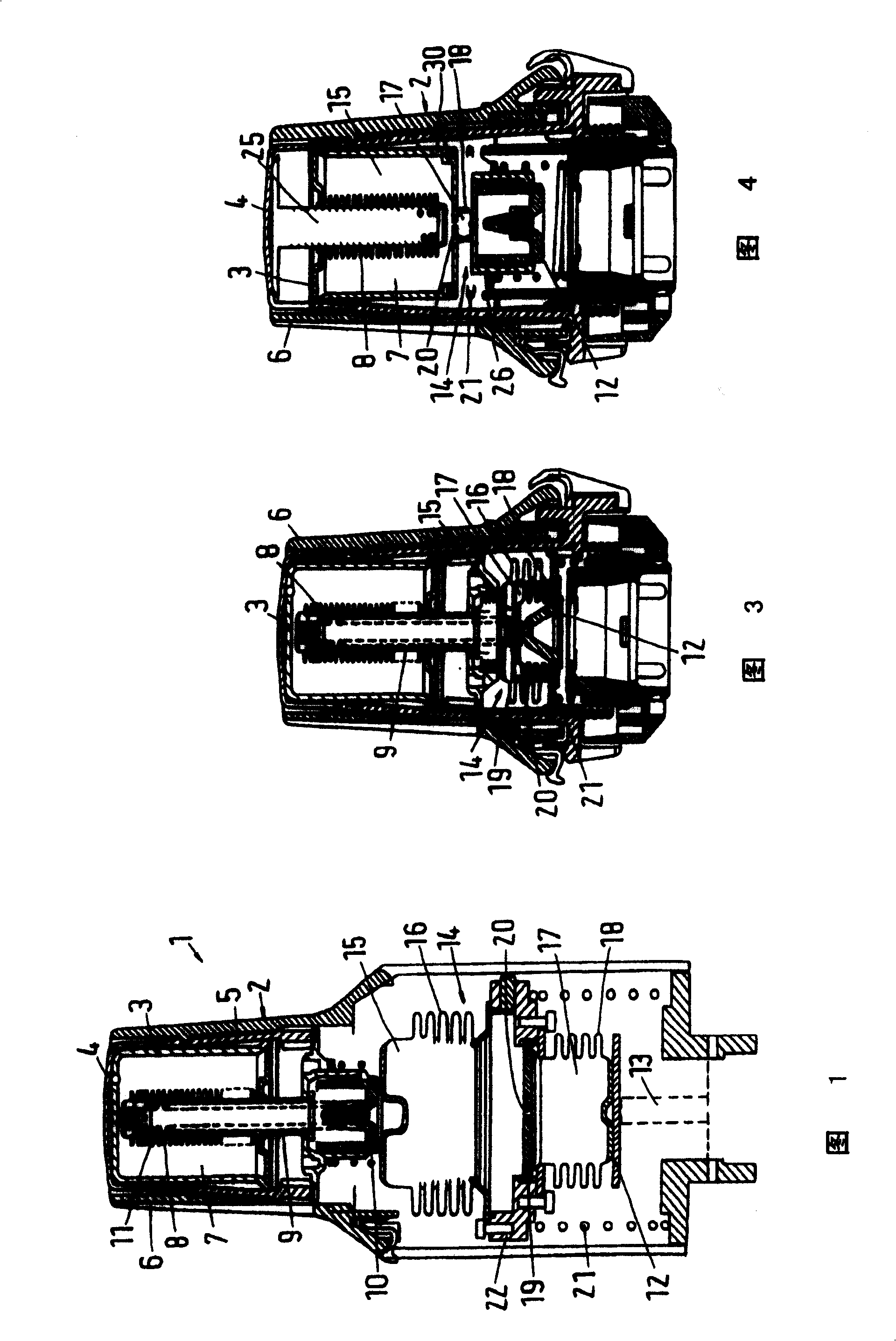
[0031] The thermostat attachment 1 has a housing 2 in which a thermostat element 3 is arranged. The thermostat element 3 is supported on a top wall 4 of the housing 2 . The top wall is formed on an insert 5 which can be moved in the axial direction by means of a rotary knob 6 in order to predetermine a temperature target value.

[0032] The thermostat element 3 has an inner chamber 7, which is filled with a thermally expandable liquid (or gas), whose volume changes with temperature. The interior space 7 is delimited on its inside by a bellows 8 . Arranged in the bellows 8 is an actuating pin 9 which interacts with a projection 10 . A high-pressure spring 11 is arranged inside the operating pin 9 .

[0033] The construction of the thermostat attachment 1 corresponds so far to that of a conventional thermostat valve attachment. When the temperature in the cavity rises and affects the thermostat element 3, the filling in the cavity 7 expands and pushes the operating pin 9 dow...


PUM


Abstract

The thermostat attachment (1) has a housing (2), a thermostat element and a correcting device (14) which is arranged in the operating strand. The effective length can be changed with a changing rate, which is smaller than the rate of change of the thermostat element (3).

Description

technical field [0001] The invention relates to a thermostat accessory for heating valves or condensation valves, which has a housing, a thermostat element and an operating element movable in the operating direction, the effective length of the thermostat element varies with the temperature Instead, the thermostat element is arranged in an operating chain between the housing and the operating element. Background technique [0002] A thermostat attachment of this type is known, for example, from DE 101 62 608 A1. In this case, the thermostat element is supported with its one end on the inner end face of the housing. The thermostat element has an expansion area in the bellows structure located on the inside. This bellows encloses an opening into which an operating element is inserted. In the assembled state, this operating element is supported on a valve plunger. When the temperature in the chamber increases and the thermostat element is acted upon, the actuating element i...

Claims


Application Information

Patent Timeline
Patent Type & Authority Patents(China)
IPC IPC(8): F16K31/68
CPCF16K31/002
Inventor B·弗雷德里克森A·B·拉森N·格雷格尔森C·阿格尔斯贝克
Owner DANFOSS AS
Why Eureka
Try Eureka