Image fixing apparatus image forming apparatus using the same

A technology for fixing belts and detection devices, which is applied to electrical recording technology using charge graphics, equipment and instruments using electrical recording technology using charge graphics, and can solve problems such as poor bonding accuracy, peeling, and the inability of the core to be close to the fixing part and other problems to achieve the effect of suppressing temperature rise and reducing variable errors

Inactive Publication Date: 2009-01-21
RICOH KK
View PDF9 Cites 0 Cited by
  • Summary
  • Abstract
  • Description
  • Claims
  • Application Information

AI Technical Summary

Problems solved by technology

However, in this case, the magnetic flux shielding member bonded to the above-mentioned core portion has a thickness such that the core portion cannot come close to the fixing member.
In addition, if the bonding accuracy of the magnetic flux shielding member to the core part is poor, the effect of suppressing the temperature rise in the non-paper-passing area cannot be sufficiently obtained.
In addition, since the ambient temperature is high, the adhesive force of the magnetic flux shielding member is low, and peeling from the core may occur.

Method used


Image

  • Image fixing apparatus image forming apparatus using the same
  • Image fixing apparatus image forming apparatus using the same
  • Image fixing apparatus image forming apparatus using the same

Examples


Embodiment 1

[0107] refer to Figure 1-Figure 8 , to describe Embodiment 1 of the present invention in detail.

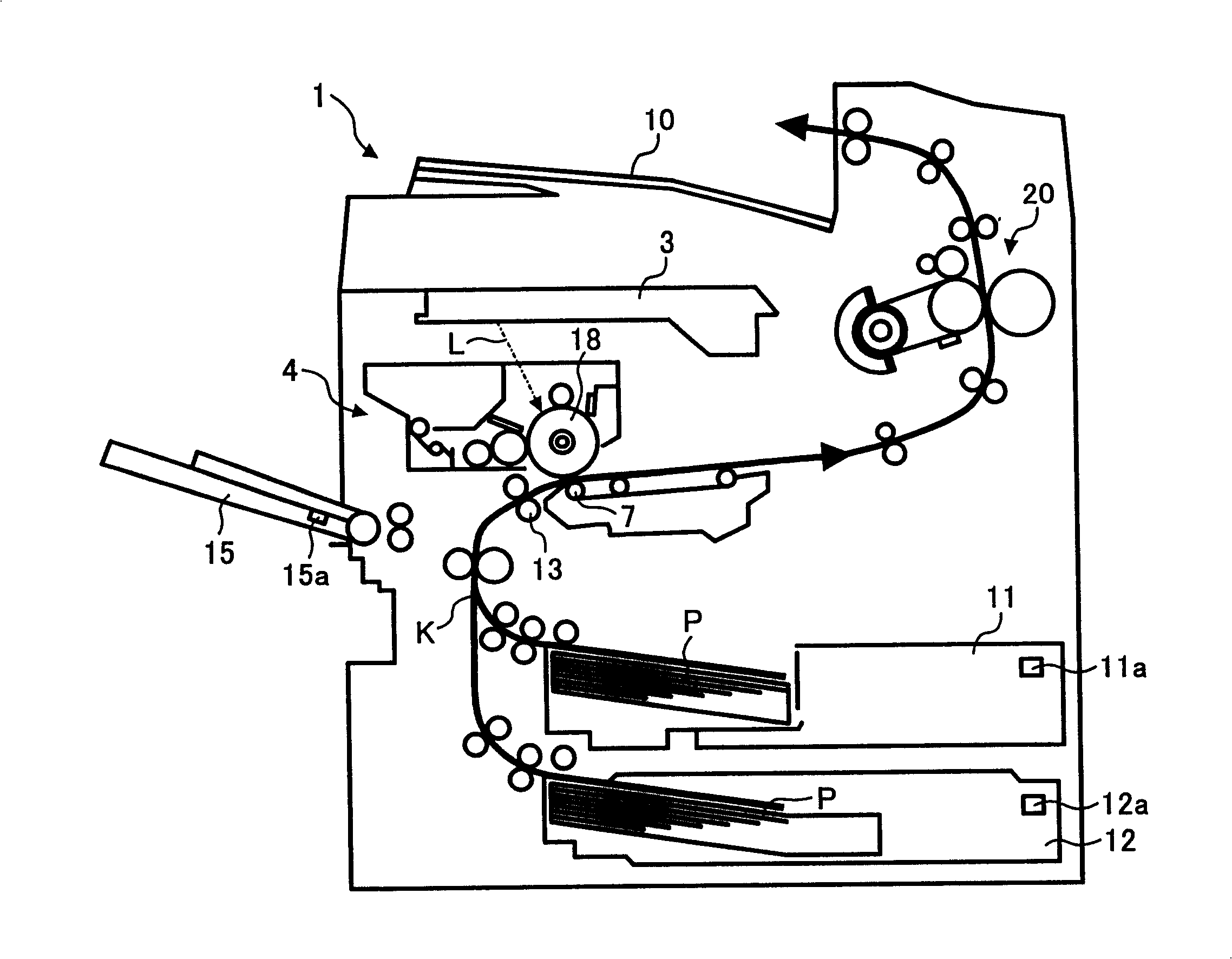
[0108] exist figure 1 In , the overall configuration and operation of the image forming apparatus will be described.

[0109] exist figure 1 Among them, symbol 1 represents the device body of a laser printer as an image forming device; symbol 3 represents an exposure unit, which irradiates the photosensitive drum 18 with an exposure light beam L based on image information;

[0110] Symbol 4 represents a process cartridge as an image forming unit, which can be attached and detached to the image forming apparatus main body 1; Symbol 7 represents a transfer unit, which transfers the toner image formed on the photosensitive drum 18 to the recording medium P; 10 denotes a discharge table on which an output image is placed; symbols 11 and 12 represent a paper feeding section for storing recording media P such as transfer paper; symbol 13 denotes a registration roller for sending th...

Embodiment 2

[0168] Embodiment 2 of the present invention will be described in detail with reference to FIG. 9 .

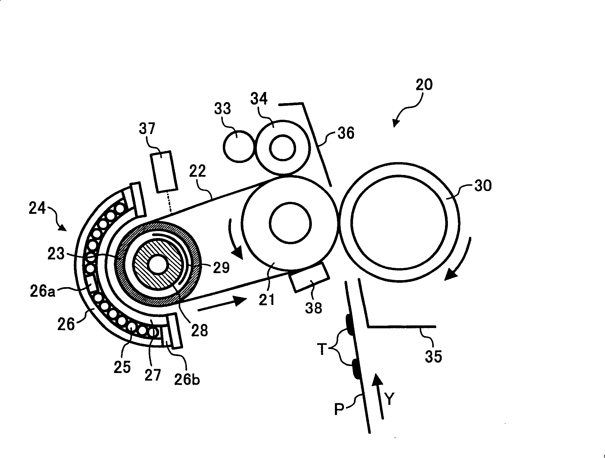
[0169] FIG. 9 shows a flowchart of control executed by the fixing device 20 of the second embodiment. In the second embodiment, the magnetic flux shielding member 29 is controlled and driven according to the temperature detected by the pyroelectric element 37 as the temperature detecting means, which is different from that in the first embodiment, where the magnetic flux shielding member 29 is controlled and driven according to the count value of the counting means.

[0170] In the flow of FIG. 9 , the control flow of steps S1 to S10 is the same as that of FIG. 5 of the first embodiment described above.

[0171] In step S10 , after the continuous paper feeding starts, the process proceeds to step S21 , where the temperature on the fixing belt 22 during the continuous paper feeding is detected by the thermoelectric element 37 . Here, the thermoelectric element 37 faces substan...

Embodiment 3

[0180] Referring to Figure 10 and Figure 11 Embodiment 3 of the present invention will be described in detail.

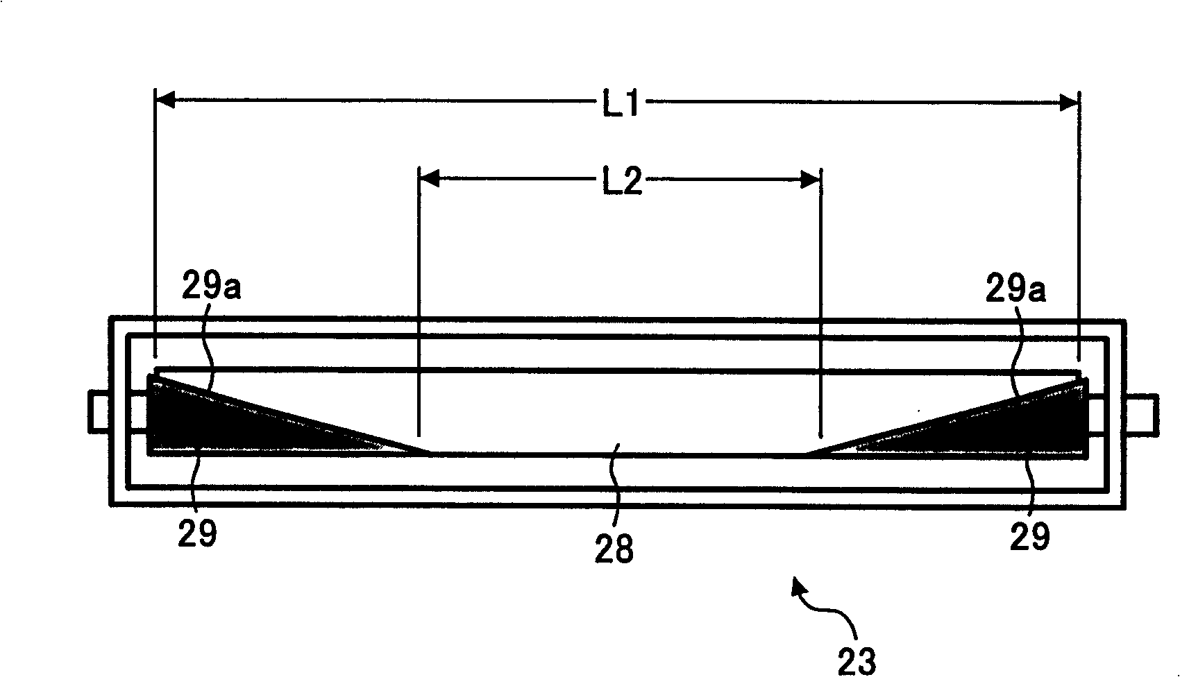
[0181] FIG. 10 shows a flow chart of control executed by the fixing device 20 of the third embodiment. In the present embodiment 3, the driving of the magnetic flux shielding member 29 is controlled according to the temperature change of the widthwise end portion of the fixing belt 22 , which is different from that of the embodiment 2 in which the driving of the magnetic flux shielding member is controlled according to the temperature change of the widthwise central portion of the fixing belt 22 . 29 different.

[0182] In the flow of FIG. 10 , the control flow of steps S1 to S10 is the same as that of FIG. 9 of the second embodiment described above.

[0183] In step S10 , after the continuous paper feeding is started, the process proceeds to step S31 , where the temperature on the fixing belt 22 during the continuous paper feeding is detected by the thermistor 3...


PUM


Abstract

The present invention relates to a fixing device, in particular to a fixing device that adopts a heating method of electromagnetic induction and an image forming device. The fixing device 20, which is used for fixing an toner image T on a recording medium P, is provided with a magnetic flux generation means 24 that is used for generating the magnetic flux, heating components 22 and 23 that are heated by induction of the magnetic flux, a magnetic flux adjusting component 29 in the width direction, the set adjustment range of which lowers the magnetic flux that affects the heating components 22 and 23; the adjusting component 29 can be driven to adjust a changeable means of changeable adjustment range. During the period of continuous fixation of the toner image T by a plurality of recording media P, the changeable means controls and drives the adjusting component 29. The present invention also provides a fixing device and an image forming device, which can reliably inhibit the temperature of the heating components or the two ends in the width direction of the fixing component, even on the occasions of continuous fixation of a plurality of recording media.

Description

technical field [0001] The present invention relates to electrophotographic image forming devices, such as copiers, printers, facsimile machines, and multifunction machines, and a fixing device provided therein, and more particularly, to a fixing device and an image forming device using electromagnetic induction heating. Background technique [0002] In the past, in copiers, printers and other image forming devices, in order to reduce the rise time of the device, for the purpose of saving energy, a fixing device using electromagnetic induction heating is known. Patent Document 1") Publication. [0003] In Patent Document 1, the fixing device of the electromagnetic induction heating method is mainly composed of a backup roller (heating roller), a fixing auxiliary roller (fixing roller), and a fixing belt (heat-resistant belt) spanned by the backup roller and the fixing auxiliary roller. The magnetic flux generating means facing the backup roller is constituted by the fixing ...

Claims


Application Information

Patent Timeline
Patent Type & Authority Patents(China)
IPC IPC(8): G03G15/20
Inventor 石井贤治网田晃康大村健长谷川健一横山博司上野智志
Owner RICOH KK
Why Eureka
Try Eureka