Rotatable tool for chip removing machining

A technology of rotating tools and chip machines, applied in the direction of tools for lathes, cutting inserts, manufacturing tools, etc., can solve the problem of the possibility of difficult to accurately center the removable top

Inactive Publication Date: 2009-01-28
SANDVIK INTELLECTUAL PROPERTY AB
View PDF6 Cites 14 Cited by
  • Summary
  • Abstract
  • Description
  • Claims
  • Application Information

AI Technical Summary

Problems solved by technology

This rotational locking in turn makes it more difficult to precisely center the removable top relative to the base

Method used


Image

  • Rotatable tool for chip removing machining
  • Rotatable tool for chip removing machining
  • Rotatable tool for chip removing machining

Examples


Embodiment Construction

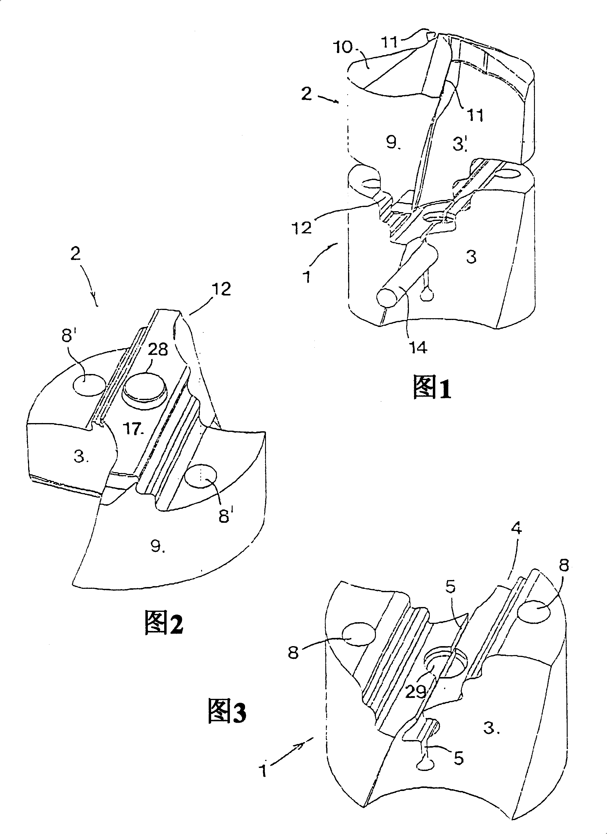
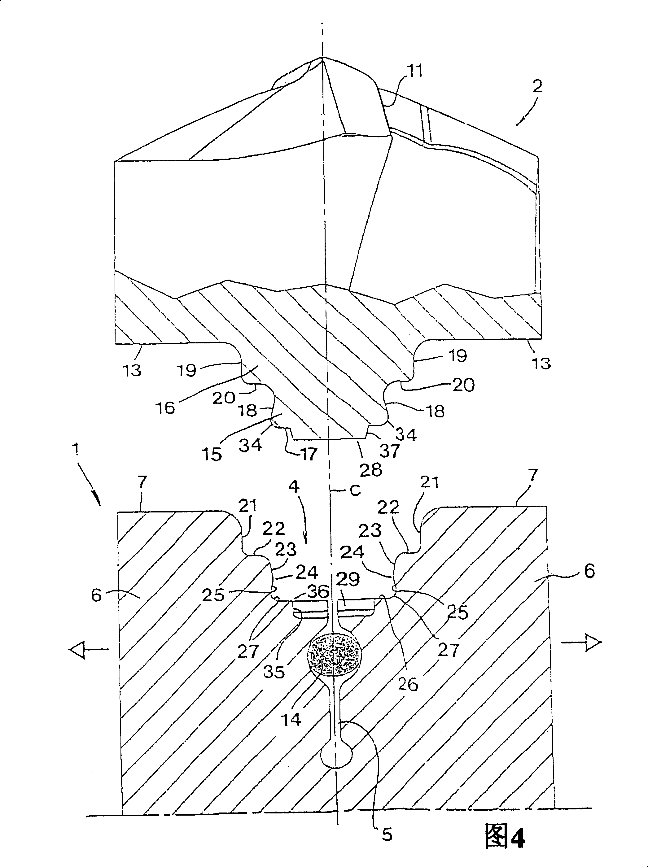
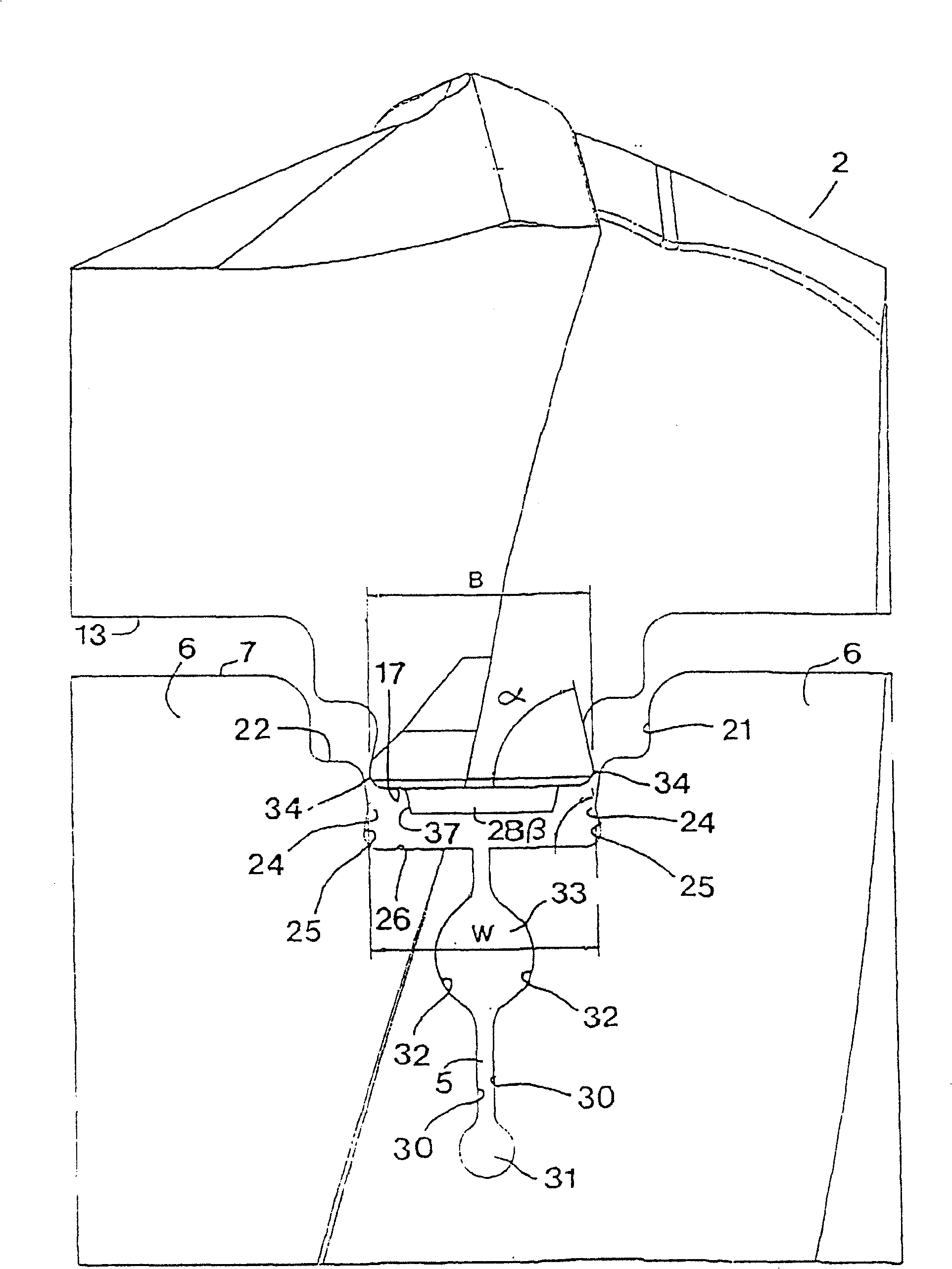
[0016] The tool shown in FIGS. 1-8 is in the form of a drill bit which generally comprises a base body generally indicated at 1 and a replaceable cutting portion or removable top 2 . The basic body 1 is formed in this case by an elongated shank with a cylindrical basic shape, which is shown in the disconnected state in these figures. The base body can be mounted in a suitable manner in a machine tool, for example a multi-operation machine tool, and has two helical, concavely curved interfaces 3 in cross-section, these delimiting surfaces forming the chip flutes. In the front or outer end of the base body 1 is formed a groove 4 in which a slit 5 is cut, which separates two elastically deflectable legs 6 . On both sides of the groove 4 there are thrust transmission surfaces 7 in which grooves 8 are cut for feeding cooling liquid to corresponding grooves 8' in the removable top 2 .

[0017] The removable top 2 has a rotationally symmetrical basic shape, here it has a circular ou...


PUM


Abstract

The invention relates to a rotatable tool for chip removing machining, of the type that comprises a basic body (1), e.g. a drill shank, and an exchangeable loose top (2). Between these there is a coupling, which includes a male part (12) on the loose top, and a groove (4) in the basic body. By means of a slot (5), two deflectable legs (6) are defined, which form a jaw for receiving and clamping of the male part (12). According to the invention, the maximal width (W) of the jaw upon deflection of the legs (6) is larger than the maximal breadth (B) of a wedge portion (15) included in the male part. Furthermore, the angles of inclination ( alpha , beta ) of flank surfaces (18) on the male part and side surfaces (25) in the groove, are equally large in order to guarantee surface contact between said surfaces, when the legs (6) resiliently are tightened against the male part. <IMAGE>

Description

technical field [0001] The present invention relates to a rotatable tool for chip removal or chip forming machining comprising a base body rotatable about a geometric central axis and replaceable cutting parts or insert bodies which can be configured by convex / concave The joint is connected to the base body, the tool comprising on the one hand a female groove formed in the front end of the base body and on the other hand a male part protruding rearwardly from the main part of the cutting part into which it can be inserted, said male part includes a front base portion defined by a pair of opposing first side surfaces and disposed adjacent the main portion, and a rear wedge-shaped portion that is slimmer than the base portion and defined by a pair of opposing second side surfaces such that in the front portion of the base A forward opening slit is formed which separates the two resiliently deflectable legs for clamping the male part in the groove, and the groove comprises two sp...

Claims


Application Information

Patent Timeline
Patent Type & Authority Patents(China)
IPC IPC(8): B23B51/00B23C5/22B23B27/16B23B51/02
CPCB23B2251/02Y10S408/713B23B2205/02B23B2260/078B23B51/02B23B2251/248Y10T408/9098Y10T408/90987Y10T408/907Y10T408/9097E06B7/36E06B7/2309E06B3/4636E05Y2800/41
Inventor 拉尔斯-奥拉·汉松
Owner SANDVIK INTELLECTUAL PROPERTY AB
Why Eureka
Try Eureka