Floor sweeping machine

A sweeper and body technology, applied in the field of sweepers, can solve the problems of high use cost, low power, poor practicability, etc., and achieve the effects of low use cost, large driving force, and strong practicability

Inactive Publication Date: 2009-02-25
伍尚强
View PDF8 Cites 6 Cited by
  • Summary
  • Abstract
  • Description
  • Claims
  • Application Information

AI Technical Summary

Problems solved by technology

[0002] There are various types of sweepers in the prior art and different structures. They are mainly divided into electric sweepers and manual sweepers. The former has certain noise and needs power consumption, and its use cost is relatively large; The friction of the brush roller is used to provide the driving force of the broom brush roller. The common disadvantages of the latter are: 1. The power is small, especially the smoother the ground, the smaller the driving force, and even the sweeper stops working due to the slippery ground; 2. The sweeper does not move, and the broom brush roller does not work; 3. Since a large part of the area in contact with the ground is occupied by the friction drive mechanism, the volume of garbage is generally small, and in actual use, it is more practical. Poor, easy to leak garbage

Method used


Image

  • Floor sweeping machine
  • Floor sweeping machine
  • Floor sweeping machine

Examples


Embodiment Construction

[0017] The present invention will be further described below in conjunction with the accompanying drawings and specific embodiments.

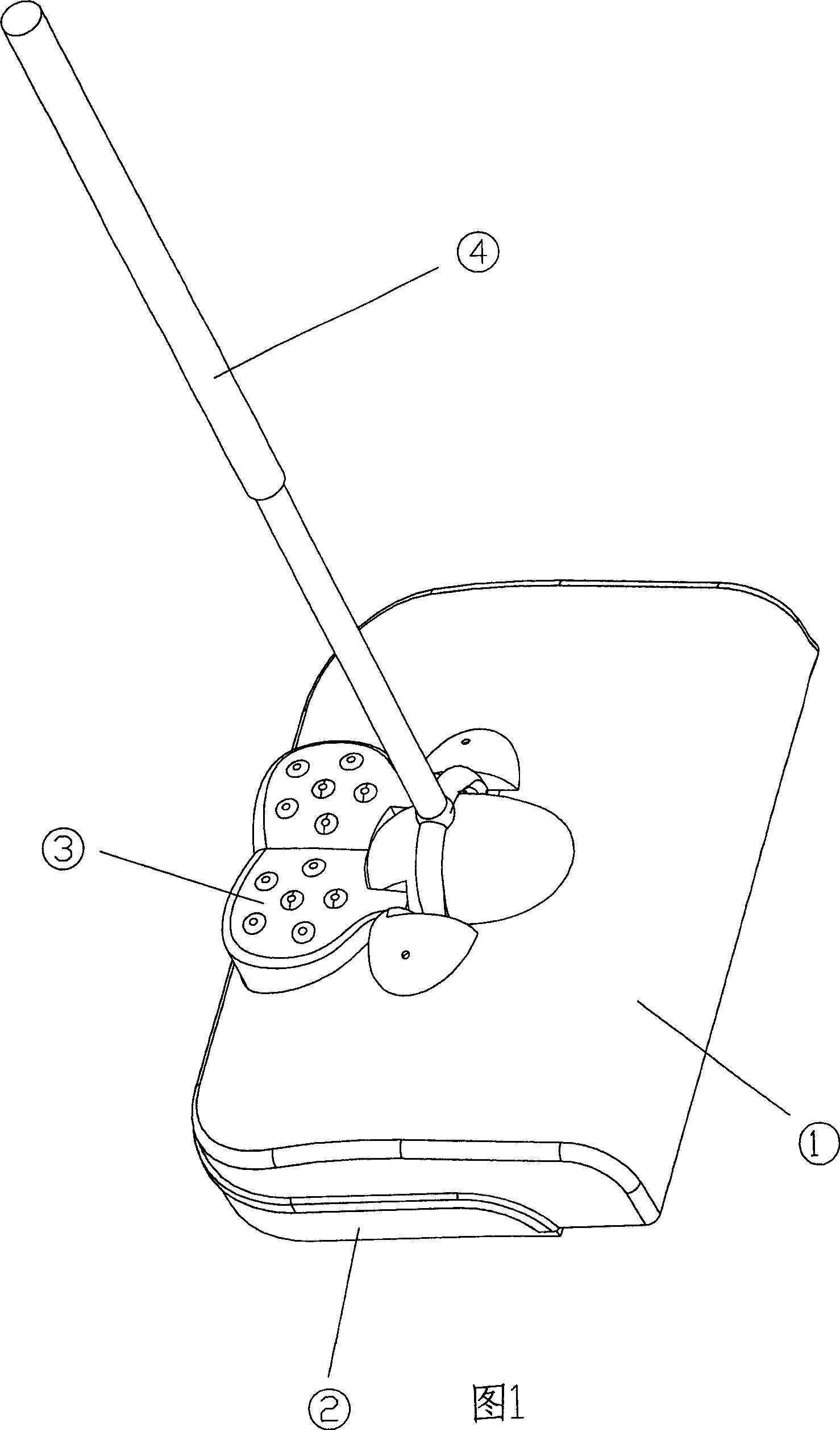
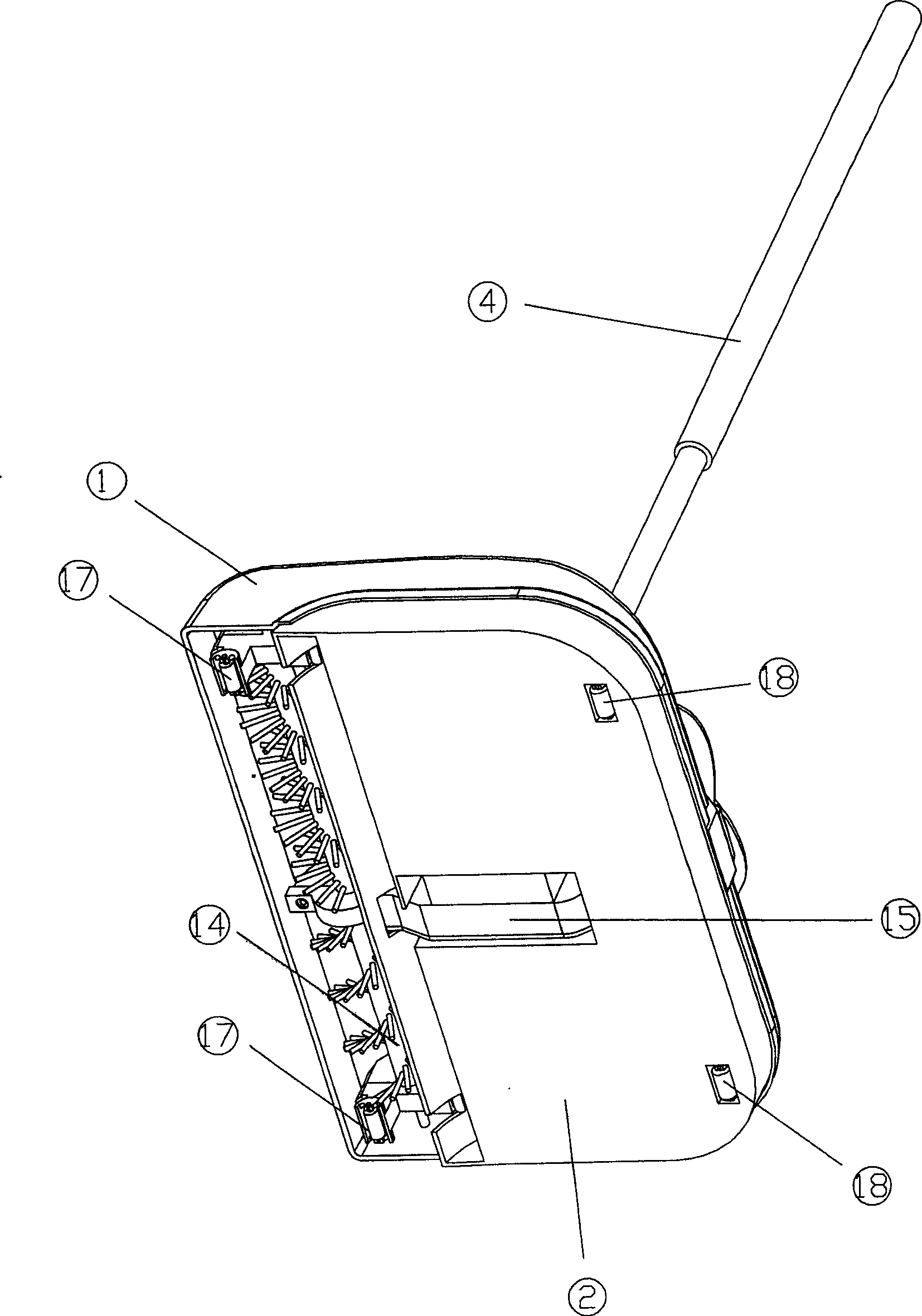
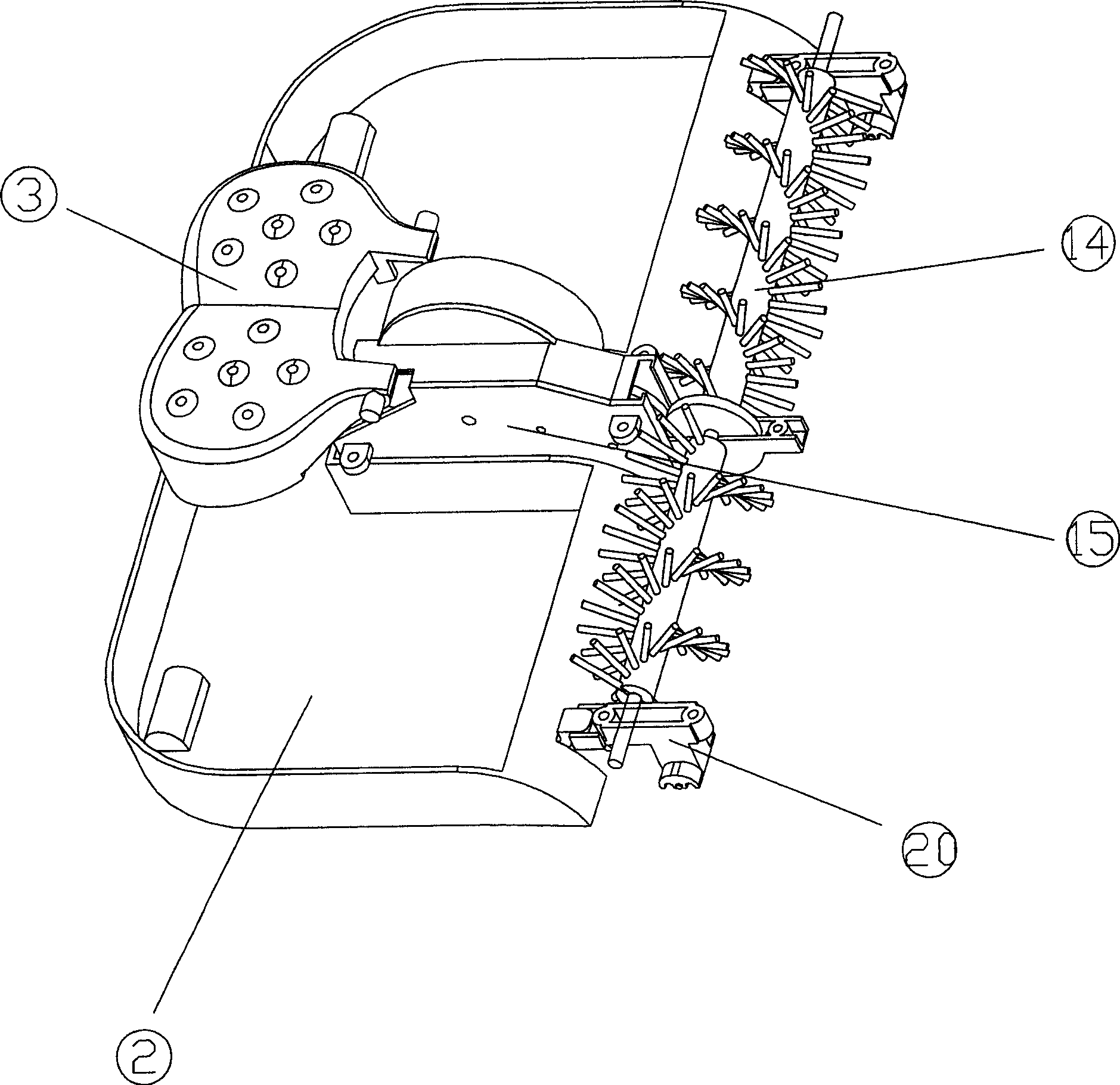
[0018] In Figure 1, figure 2 Among them, the body is formed by connecting the upper cover 1 and the garbage shovel 2 arranged at the bottom of the upper cover 1 using conventional structures such as male and female joints (not shown in the figure). The handle 4 is hinged on the top of the upper cover 1 . The axles of two front casters 17 are contained in the bottom of mounting bracket 20, and mounting bracket 20 is located at the two ends of garbage shovel 2 front sides. Two rear casters 18 then pass the hole of the garbage shovel 2 and its axle is installed on the garbage shovel 2.

[0019] Such as image 3 , Figure 4 ,Figure 5, Figure 6 shown.

[0020] Pedal 3 is positioned at loam cake 1 hole, and the both sides of its front end are hinged on loam cake 1, and pedal 3 bottom is fixedly connected with thumb wheel 5. Back-moving spring...


PUM


Abstract

The invention relates to a cleaning machine which comprises a host and a handle, a driving plate and relative return spring mounted in the mounting hole of host and hinged with the host, a dial wheel fixed with the driving plate, a besom element rotationally mounted at the waste inlet of host, an inertia flywheel and gear group mounted in the host. The gears of gear group are meshed with the dial wheel, the driving wheel of besom and the clutch of inertia flywheel. The invention is powered by the inertia flywheel, without consuming electricity and affected by the smoothness of floor, while it has large waste volume.

Description

technical field [0001] The invention relates to a ground cleaning machine, in particular to a sweeping machine. Background technique [0002] There are various types of sweepers in the prior art and different structures. They are mainly divided into electric sweepers and manual sweepers. The former has certain noise and needs power consumption, and its use cost is relatively large; The friction of the brush roller is used to provide the driving force of the broom brush roller. The common disadvantages of the latter are: 1. The power is small, especially the smoother the ground, the smaller the driving force, and even the sweeper stops working due to the slippery ground; 2. The sweeper does not move, and the broom brush roller does not work; 3. Since a large part of the area in contact with the ground is occupied by the friction drive mechanism, the volume of garbage is generally small, and in actual use, it is more practical. Poor, also easy to leak garbage. Contents of t...

Claims


Application Information

Patent Timeline
Patent Type & Authority Patents(China)
IPC IPC(8): A47L11/22
Inventor 伍尚强
Owner 伍尚强
Why Eureka
Try Eureka