Parallel type two-phase full wave brushless DC motor

A DC motor, parallel technology, applied in the direction of electrical components, electromechanical devices, etc., can solve the problems of large motor internal space, high manufacturing cost of high rated power drive components, and increased manufacturing costs

Inactive Publication Date: 2009-03-18
SUNONWEALTH ELECTRIC MACHINE IND
View PDF5 Cites 0 Cited by
  • Summary
  • Abstract
  • Description
  • Claims
  • Application Information

AI Technical Summary

Problems solved by technology

Thus, when the rated power of the driving element 11 is increased, the driving element 11 has the disadvantage of occupying too much internal space of the motor
[0004] In addition, the manufacturing cost of the high-rated power driving element is quite high, which exceeds the manufacturing cost of two small-rated power driving elements, so the high-rated power driving element has the disadvantage of increasing the manufacturing cost

Method used


Image

  • Parallel type two-phase full wave brushless DC motor
  • Parallel type two-phase full wave brushless DC motor
  • Parallel type two-phase full wave brushless DC motor

Examples


Embodiment Construction

[0032] In order to further understand the technical solutions, features and advantages of the present invention, preferred embodiments of the present invention will be described in detail below together with the accompanying drawings.

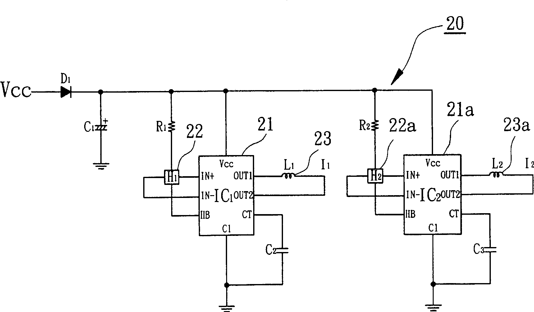
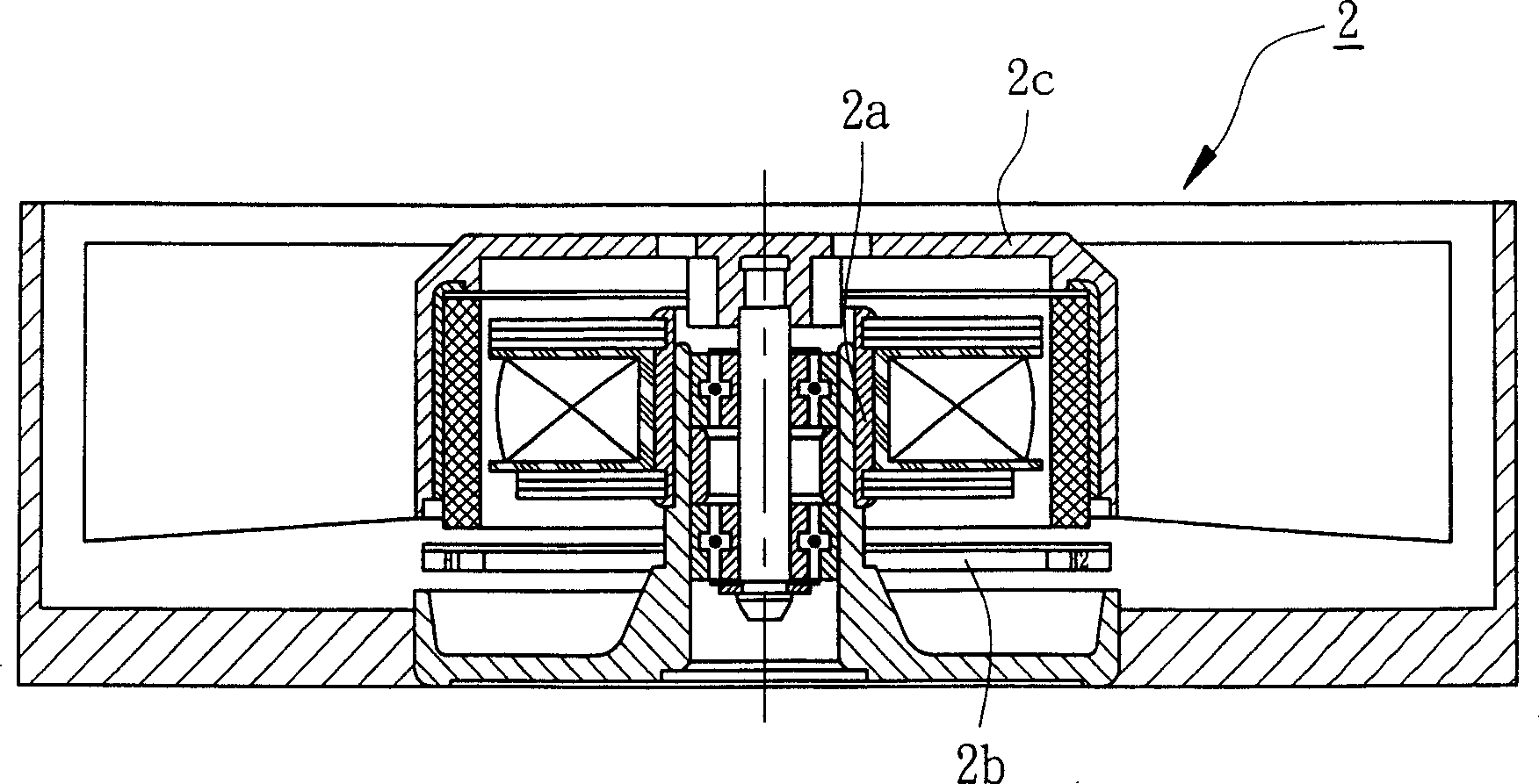
[0033] figure 2 A schematic circuit diagram of a parallel dual-phase full-wave brushless DC motor according to the first preferred embodiment of the present invention is disclosed. image 3 A cross-sectional view of a parallel dual-phase full-wave brushless DC motor according to the first preferred embodiment of the present invention is disclosed.

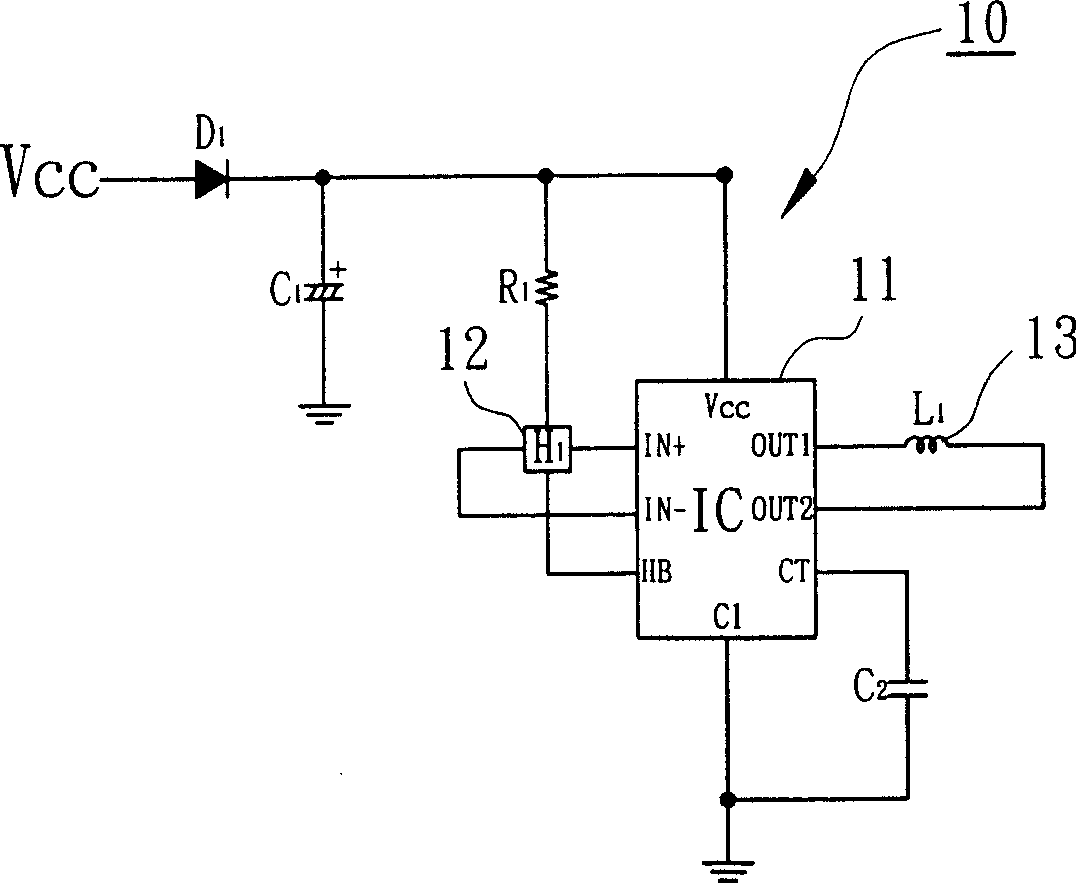
[0034] Please refer to figure 2 and image 3 As shown, the parallel dual-phase full-wave brushless DC motor 2 of the preferred embodiment of the present invention has a parallel dual-phase full-wave drive circuit 20 . The parallel dual-phase full-wave driving circuit 20 includes a first driving element 21 , a second driving element 21 a , a first inductive element 22 , a second inductive elemen...


PUM


Abstract

The parallel diphase full-wave brushless DC motor comprises a first and second drive element, a first and second induction element, and a first and second coil; wherein, the first drive element connects to the first induction element and coil, and controls the first current conducting direction of first coil by Hall signal from first induction element to make first coil generate full-wave excitation; so does the second drive element to induction element and coil; the first drive element parallels with the second drive element to parallel the first and second coil for synchronous excitation. Thereby, this invention can increase motor rated power, has little volume and low cost.

Description

technical field [0001] The invention relates to a parallel dual-phase full-wave brushless DC motor, in particular to a parallel dual-phase full-wave brushless DC motor controlled by two sensor / drive members. Background technique [0002] Please refer to figure 1 As shown, it discloses a circuit diagram of a known single-phase full-wave brushless DC motor. The single-phase full-wave brushless DC motor has a single-phase full-wave driving circuit 10 , and the single-phase full-wave driving circuit 10 includes a driving element 11 , an inductive element 12 and a coil 13 . The driving element 11 is electrically connected to the inductive element 12 and the coil 13 , and controls the conduction direction of the coil 13 through the Hall signal of the inductive element 12 . Therefore, the coil 13 forms a full-wave excitation in both conduction directions to drive a rotor to rotate. [0003] However, the rate of change between the rated power / current [rated power / current] and the...

Claims


Application Information

Patent Timeline
Patent Type & Authority Patents(China)
IPC IPC(8): H02K29/08
Inventor 洪银树洪庆升葛大伦
Owner SUNONWEALTH ELECTRIC MACHINE IND
Why Eureka
Try Eureka