
Demodulator and demodulation method for demodulating received signals

A demodulator and signal converter technology, which is applied in the demodulation, demodulation, and oscillation conversion angle demodulation of angle modulation oscillation, can solve the problems of high cost and difficulty of the quadrature correlator, and achieves simple structure and manufacturing. The effect of cost reduction and chip area reduction

Inactive Publication Date: 2009-03-18
INTEL MOBILE COMM GMBH
View PDF5 Cites 0 Cited by
  • Summary
  • Abstract
  • Description
  • Claims
  • Application Information

AI Technical Summary

Problems solved by technology

Subsequent filtering that can mask this interfering signal becomes difficult
Another disadvantage is that in the circuit system, the implantation required to use the quadrature correlator is quite expensive

Method used


Image

  • Demodulator and demodulation method for demodulating received signals
  • Demodulator and demodulation method for demodulating received signals
  • Demodulator and demodulation method for demodulating received signals

Examples


Embodiment Construction

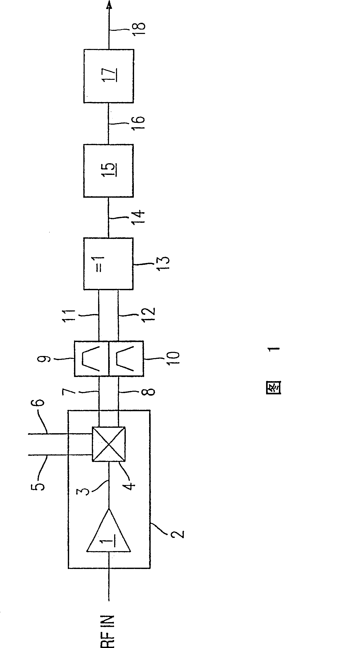
[0040] Figure 1 illustrates a first embodiment of the invention. In this example, the received radio frequency signal RF IN is sent to the amplifier 1 of the radio frequency unit 2 . The amplified radio frequency signal 3 is passed to a mixer 4 and is down-converted into an intermediate frequency range with the aid of two signals 5 and 6 of a zone oscillator, said signals being phase shifted at 90 degrees to each other. Thus, two intermediate frequency signals are generated, namely the in-phase signal 7 and the quadrature signal 8 , which are then provided to a channel for filtering to mask signal components outside the intermediate frequency range. For this purpose, a channel filter 9 is provided for the in-phase signal and a channel filter 10 for the quadrature signal, at the output of the filter it is possible to tap off the channel-filtered in-phase signal 11 and the filtered The quadrature signal 12. Channel filters 9 and 10 may be composite bandpass filters which, in a...


PUM


Abstract

The invention relates to a demodulator and also a demodulation method and enables a reliable demodulation even when the intermediate frequency range overlaps the range of the data frequencies of the signal. For this purpose, a rapidly oscillating output signal is generated from the in-phase signal and also the quadrature signal, the sign of which output signal varies in a manner dependent on the product of the signs of the in-phase signal and of the quadrature signal. Either an XOR gate or a multiplier stage may be used in order to generate an output signal of this type.

Description

technical field [0001] The invention relates to a demodulator for demodulating radio frequency signals, and in particular for demodulating mobile radio signals. Furthermore, the invention relates to a method for demodulating radio frequency signals. Background technique [0002] In order to be able to demodulate the received signal transmitted through a wireless channel, usually the RF received signal is first down-converted to a lower frequency. Further signal processing is then performed at this intermediate frequency. In this example, the received signal may be down-converted to frequency zero, or down-converted to an intermediate frequency other than zero. After the signal has been down converted, it must be ensured that only those signal components which are in the frequency band defined by the channel are sent to the next processing stage. For this purpose, a channel filter is provided which suppresses undesired frequency components. The channel filter may be a ban...

Claims


Application Information

Patent Timeline
Patent Type & Authority Patents(China)
IPC IPC(8): H03D3/04H03D3/00
CPCH03D3/007
Inventor C·格雷温格M·哈梅斯A·汉科S·范瓦亚森
Owner INTEL MOBILE COMM GMBH
Learn More