
Orbiting vane compressor

一种旋转叶片、压缩机的技术,应用在旋转活塞式机械、旋转活塞式泵、旋转活塞式/摆动活塞式的泵部件等方向

Inactive Publication Date: 2009-03-25
LG ELECTRONICS INC
View PDF7 Cites 0 Cited by
  • Summary
  • Abstract
  • Description
  • Claims
  • Application Information

AI Technical Summary

Problems solved by technology

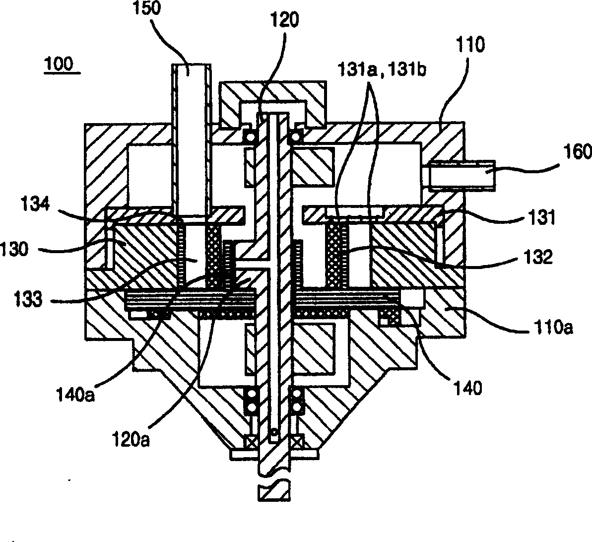
[0012] When the inner and outer air outlet holes 131a and 131b formed on the cylinder head 131 are arranged near the air outlet pipe 160 of the upper case 110, excessive oil may flow out through the air outlet pipe 160

Method used


Image

  • Orbiting vane compressor
  • Orbiting vane compressor
  • Orbiting vane compressor

Examples


Embodiment Construction

[0039] Now, preferred embodiments of the present invention will be described in detail with reference to the accompanying drawings.

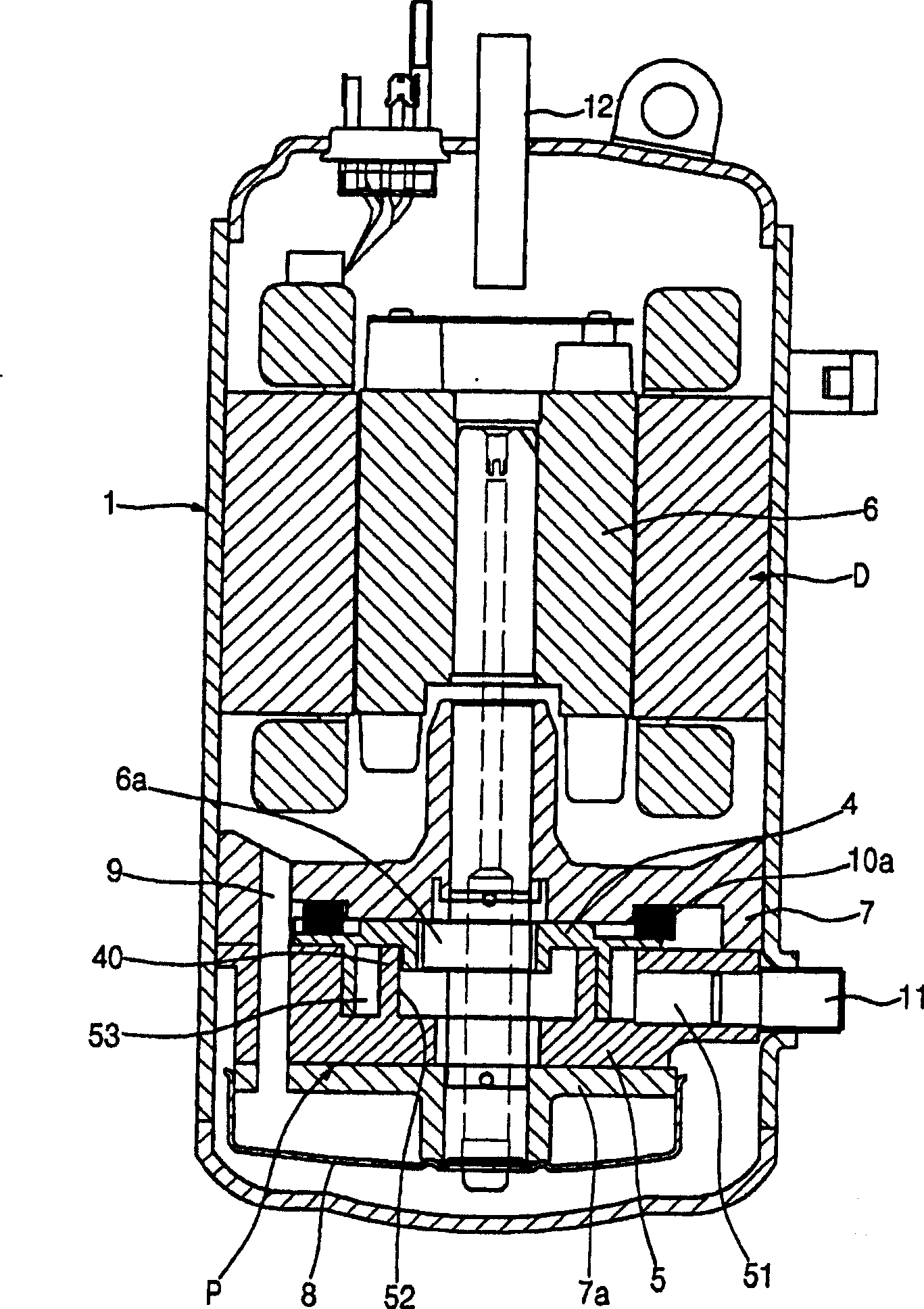
[0040] figure 2 is a longitudinal sectional view illustrating the overall structure of the hermetically sealed rotary vane compressor according to the first preferred embodiment of the present invention.

[0041] Such as figure 2 As shown, the driving part D and the compressing part P are mounted in the housing 1 while the driving part D and the compressing part P are sealed. The driving part D is disposed above the inside of the housing 1 , and the compression part P is disposed below the inside of the housing 1 . The drive part D and the compression part P are connected to each other by a vertical shaft 6 . The rotary shaft 6 has an eccentric portion 6a.

[0042] The driving part D includes: a stator 2 fixedly provided in a housing 1 ; and a rotor 3 provided in the stator 2 , which rotates a rotating shaft 6 vertically extending through ...


PUM


Abstract

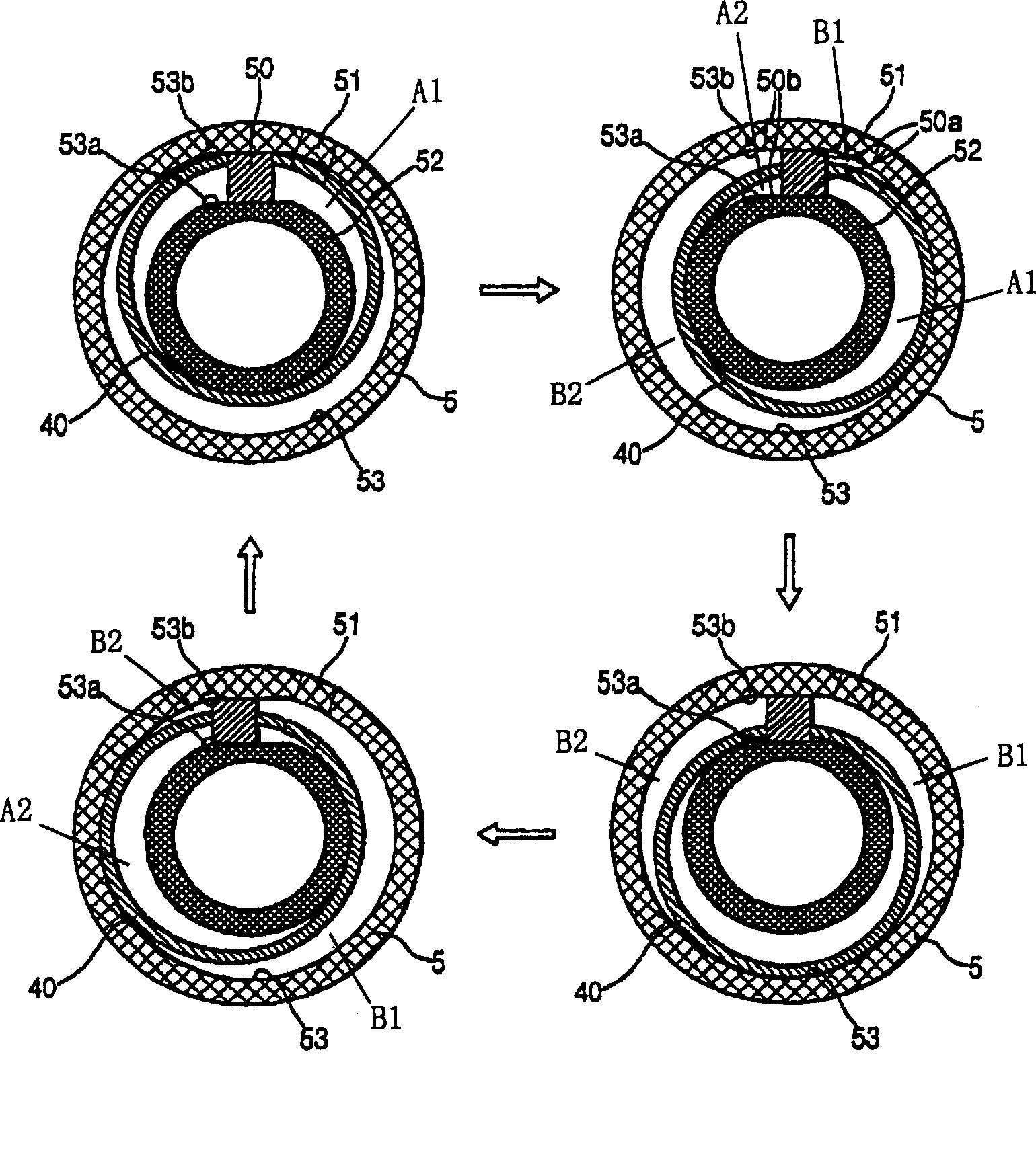
Disclosed herein is an orbiting vane compressor having two compression chambers formed in a cylinder according to an orbiting movement of an orbiting vane. The orbiting vane compressor comprises a shell having an inlet tube and an outlet tube, the shell being hermetically sealed such that refrigerant gas is introduced through the inlet tube and is then discharged through the outlet tube, a rotary shaft disposed in the shell while being supported by upper and lower flanges, the rotary shaft being rotated by a drive unit, and a compression unit for compressing refrigerant gas introduced into a cylinder according to an orbiting movement of an orbiting vane, which is attached to the rotary shaft, and discharging the compressed refrigerant gas to the lower part of the cylinder.

Description

technical field [0001] The present invention relates to a rotary vane compressor, in particular to a rotary vane compressor having two pressurized chambers which are formed in the cylinder with the rotation of the rotary vanes, thereby having a single Compression capacity and performance are improved compared to existing rotary compressors with pressurized chambers, oil is easily supplied to rotary vane compressors, and oil is easily separated from discharge gas. Background technique [0002] Generally, a vane compressor compresses air introduced into a cylinder as the vanes rotate. figure 1 It is a longitudinal sectional view describing the overall structure of a conventional vane compressor. [0003] Such as figure 1 As shown, the vane compressor includes a compression member 100 connected by a shaft 120 to a drive member (not shown). The compression part 100 is hermetically sealed by the upper and lower cases 110 and 110a. The compression part 100 is provided with a r...

Claims


Application Information

Patent Timeline
Patent Type & Authority Patents(China)
IPC IPC(8): F04C29/02F04C18/344
CPCF04C18/02F04C23/008F04C2230/60F04C2230/20F04C2240/30F04C18/045F04C18/344F04C18/356
Inventor 黄善雄刘东原
Owner LG ELECTRONICS INC
Learn More