
Backflow type air compressor and engine

A compressor and sleeve technology, which is applied to machines/engines, liquid fuel engines, gas turbines, etc., can solve the problems of aggravating compressor cooling, increasing parts, and increasing axial dimensions, shortening the axial dimensions, increasing the Compression capacity, effect of reducing airflow velocity

Active Publication Date: 2020-09-22
NANCHANG HANGKONG UNIVERSITY +1
View PDF5 Cites 0 Cited by
  • Summary
  • Abstract
  • Description
  • Claims
  • Application Information

AI Technical Summary

Problems solved by technology

[0003] However, increasing the number of stages of the compressor will increase the number of parts, and the increase in the axial dimension will greatly weaken the overall reliability of the compressor; increasing the single-stage compression ratio will have a very high requirement for the improvement of the performance of the blade material; increasing the bearing speed in addition to In addition to high requirements for bearing materials, it also puts forward more stringent performance requirements for the compressor efficiency of the blades at higher speeds; as for the realization of multi-stage bearings, although it will make the cooperation between the compressors more efficient, it will also Increased mechanical complexity will cause a significant decrease in overall reliability, which is not conducive to maintenance. In addition, the above development direction will inevitably aggravate the cooling problem of the compressor more or less

Method used


Image

  • Backflow type air compressor and engine
  • Backflow type air compressor and engine
  • Backflow type air compressor and engine

Examples


Embodiment Construction

[0033] The following will clearly and completely describe the technical solutions in the embodiments of the present invention with reference to the accompanying drawings in the embodiments of the present invention. Obviously, the described embodiments are only some, not all, embodiments of the present invention. Based on the embodiments of the present invention, all other embodiments obtained by persons of ordinary skill in the art without making creative efforts belong to the protection scope of the present invention.

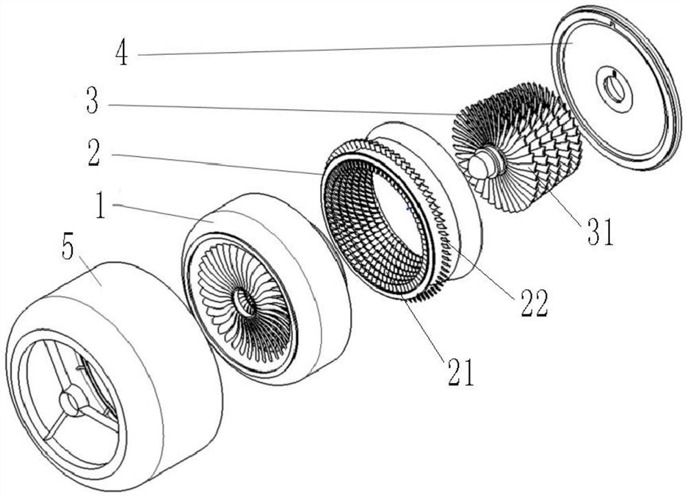
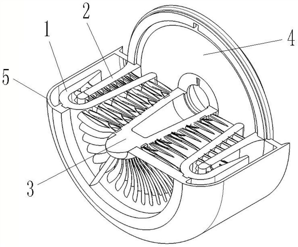
[0034] The object of the present invention is to provide a recirculation compressor and its engine to solve the problems in the prior art, to improve the compressor's compression capacity, thereby increasing the power of the engine, and shortening the axial dimension of the engine.

[0035] In order to make the above objects, features and advantages of the present invention more comprehensible, the present invention will be further described in detail below in ...


PUM


Abstract

The invention discloses a backflow type air compressor and an engine. The backflow type air compressor comprises a U-shaped sleeve rotor, wherein the U-shaped sleeve rotor comprises an inner barrel, an outer barrel and an annular barrel bottom connected between the inner barrel and the outer barrel; an end cover is arranged on the opening side of the U-shaped sleeve rotor, an inner duct stator andan outer duct stator are arranged between the end cover and the U-shaped sleeve rotor, the inner duct stator is arranged in the middle of the inner barrel, and the outer duct stator is arranged between the inner barrel and the outer barrel. A low-pressure air compression section is formed between the inner barrel and the inner duct stator, and a high-pressure air compression section is formed between the inner barrel and the outer duct stator. Air flow flows back into the high-pressure air compression section after passing through the low-pressure air compression section, and then is discharged after flowing back again. The air compression capacity of the air compressor can be improved, the power of the engine is further improved, and the axial size of the engine can be shortened.

Description

technical field [0001] The invention relates to the field of engines, in particular to a return type air compressor and its engine. Background technique [0002] With the continuous development of the aviation industry, the performance of aircraft has become more and more excellent, and the requirements for engine performance have also increased. In order to meet the demand for higher power of the engine, it is imperative to improve the compression capacity of the engine compressor, especially the efficiency. The main direction of the existing compressor development: increase the number of compressor stages, increase the single-stage compression ratio, increase the bearing speed, and realize multi-stage bearings. [0003] However, increasing the number of stages of the compressor will increase the number of parts, and the increase in the axial dimension will greatly weaken the overall reliability of the compressor; increasing the single-stage compression ratio will have a v...

Claims


Application Information

Patent Timeline
IPC IPC(8): F04D29/54F02C3/06
CPCF02C3/06F04D29/541
Inventor 皇甫乃章杨蓓马春香陈伟张贤锦刘序理张珍珍
Owner NANCHANG HANGKONG UNIVERSITY
Learn More