
Electric compressor

An electric compressor, compression chamber technology, used in machines/engines, liquid fuel engines, rotary piston machines, etc., to address the inability to adequately support the orbiting scroll, the increased size and weight of the compressor, and the number of compressor parts Increase and other problems, to achieve the effect of increasing the diameter, increasing the compression capacity, and suppressing the axial leakage

Active Publication Date: 2019-11-12
LG ELECTRONICS INC
View PDF8 Cites 0 Cited by
  • Summary
  • Abstract
  • Description
  • Claims
  • Application Information

AI Technical Summary

Problems solved by technology

[0005] However, in the conventional electric compressor as mentioned above, as mentioned above, along with the rear cover body forming the discharge space is provided on the side of the compression part including the fixed scroll, not only the number of parts constituting the compressor increase, and there is also the problem of increasing the size and weight of the compressor
Considering that electric compressors are mainly used in vehicles, the above problems may become a very disadvantageous condition
[0006] In addition, since the conventional electric compressor needs to separate oil in the discharge space, an additional oil separation device is required, and there is a problem that the number of parts increases accordingly.
[0007] In addition, the existing electric compressors only use the back pressure of the back pressure space or intermediate pressure space formed between the main frame and the orbiting scroll to axially support the orbiting scroll, which may cause problems such as When the back pressure on the orbiting scroll is small at startup, the orbiting scroll cannot be fully supported and axial leakage occurs
[0008] In addition, in the existing electric compressor, the fixed scroll is inserted into the casing. Therefore, under the condition that the outer diameter of the compressor is the same, the outer diameter of the fixed scroll is limited, which may cause a corresponding degree of Not conducive to expanding the compression capacity

Method used


Image

  • Electric compressor
  • Electric compressor
  • Electric compressor

Examples


Embodiment Construction

[0056] Next, the electric compressor of the present invention will be described in detail according to an embodiment shown in the drawings.

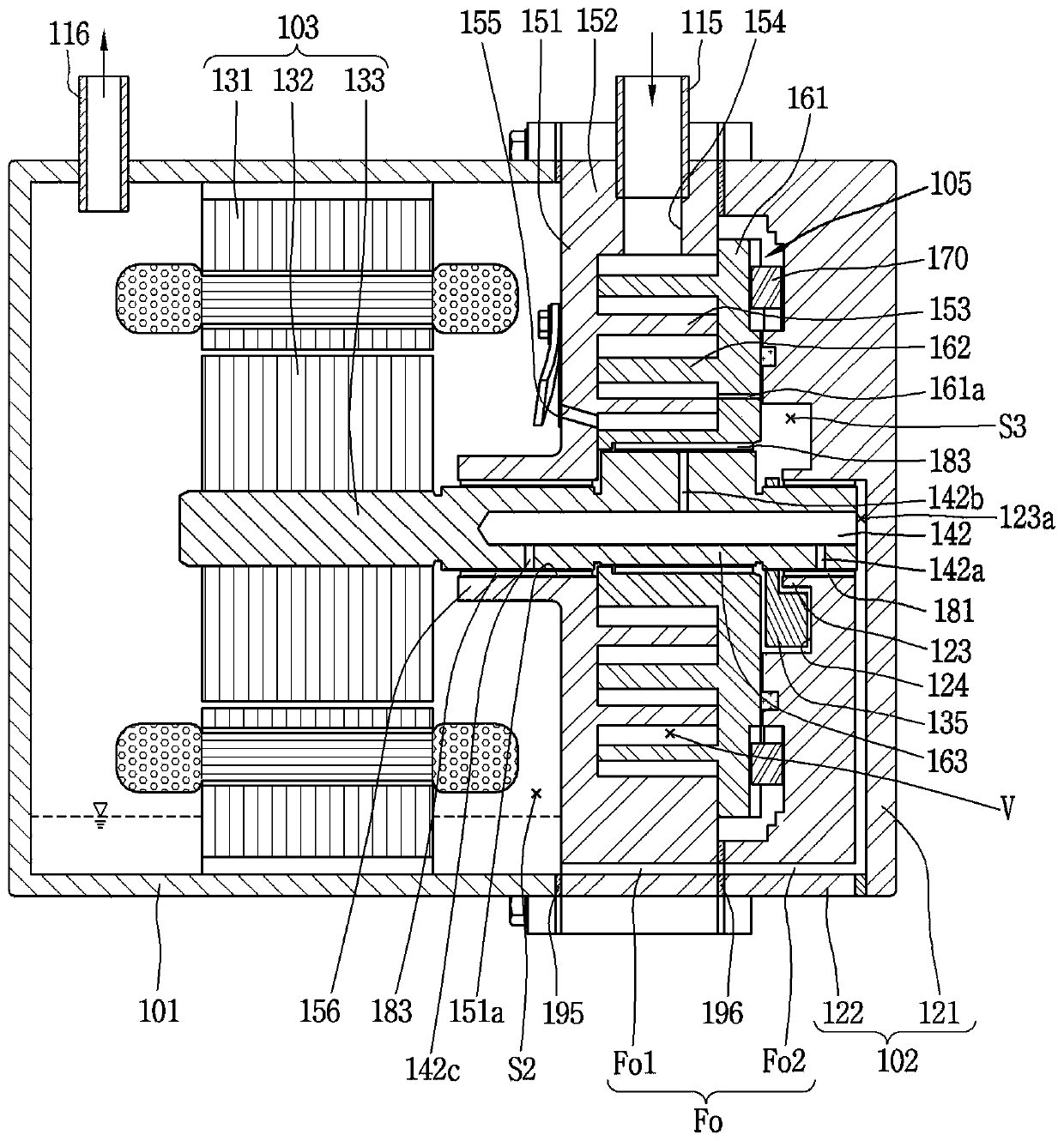
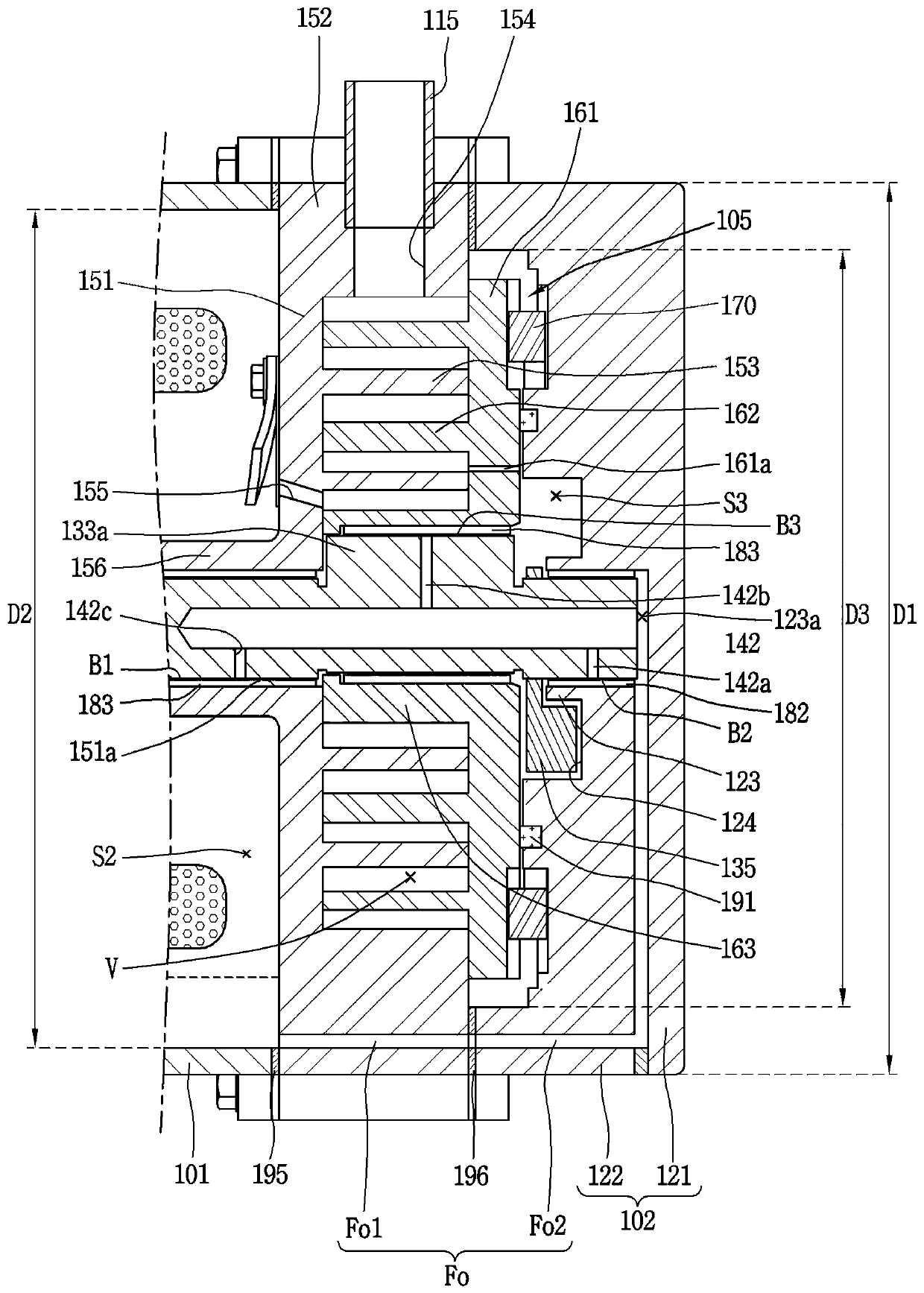
[0057] figure 1 It is a sectional view showing the inside of the electric compressor of the present invention, figure 2 will be figure 1 An enlarged and shown cross-sectional view of the periphery of the compression portion shown.

[0058] As shown in the figure, the electric scroll compressor of this embodiment (hereinafter referred to as the electric compressor) includes: a drive motor 103, which is fixed inside the cover body 101 as an electric part; and the frame 102 is provided on one side of the compression part 105 and supports the compression part 105 while playing a role of a shell together with the cover 101. Such an electric compressor is a high-pressure compressor as the refrigerant discharged from the compression unit 105 is discharged to the outside through the internal space of the cover 101 .

[0059] Along with the ...


PUM


Abstract

An electric compressor of the present invention may comprise a cover body; a driving motor which is arranged in the internal space of the cover body and is provided with a stator and a rotor; a rotating shaft coupled to the rotor; a first scroll provided on one side of the drive motor, the first scroll being rotatably coupled to the rotating shaft so as to penetrate the rotating shaft; a second scroll coupled to the first scroll and coupled to an eccentric portion of a rotating shaft penetrating through the first scroll to form a compression chamber between the second scroll and the first scroll; and a frame that is disposed on the opposite side of the drive motor from the first scroll with a second scroll interposed therebetween, supports the second scroll in the axial direction, and supports one end of a rotating shaft that passes through the second scroll in the radial direction.

Description

technical field [0001] The present invention relates to an electric compressor (MOTOR OPERATED COMPRESSOR). Background technique [0002] Among various compression methods, electric compressors mainly use the scroll compression method suitable for high compression ratio operation. This scroll-type electric compressor is provided with an electric part composed of a rotary motor inside a sealed casing, and a compression part composed of a fixed scroll and an orbiting scroll is provided on one side of the electric part. , and the electric part and the compression part are connected with a rotating shaft, and thus the rotational force of the electric part is transmitted to the compression part. The rotational force transmitted to the compression part makes the orbiting scroll orbit relative to the fixed scroll to form two paired compression chambers consisting of a suction chamber, an intermediate pressure chamber, and a discharge chamber, and compresses to both sides respectiv...

Claims


Application Information

Patent Timeline
Patent Type & Authority Applications(China)
IPC IPC(8): F04C18/02F04C27/00F04C29/00F04C29/02
CPCF04C18/0215F04C27/00F04C29/0092F04C29/02F04C29/026F04C2240/20F04C2240/30F04C23/008F04C29/023F04C2240/52F04C2240/807F04C27/005F04C29/12F04C2240/50F04C2240/603F04C2240/70F04C14/24F04C23/005F04C2240/40F04C2240/54
Inventor 朴正勋李丙哲张基泰许钟泰
Owner LG ELECTRONICS INC
Learn More