Driving apparatus for a motor
A technology for driving devices and electric motors, applied in the direction of controlling electromechanical transmission devices, motor generators/starters, motor generator control, etc. common reducing effect
- Summary
- Abstract
- Description
- Claims
- Application Information
AI Technical Summary
Problems solved by technology
Method used
Image
Examples
Embodiment 1
[0017]
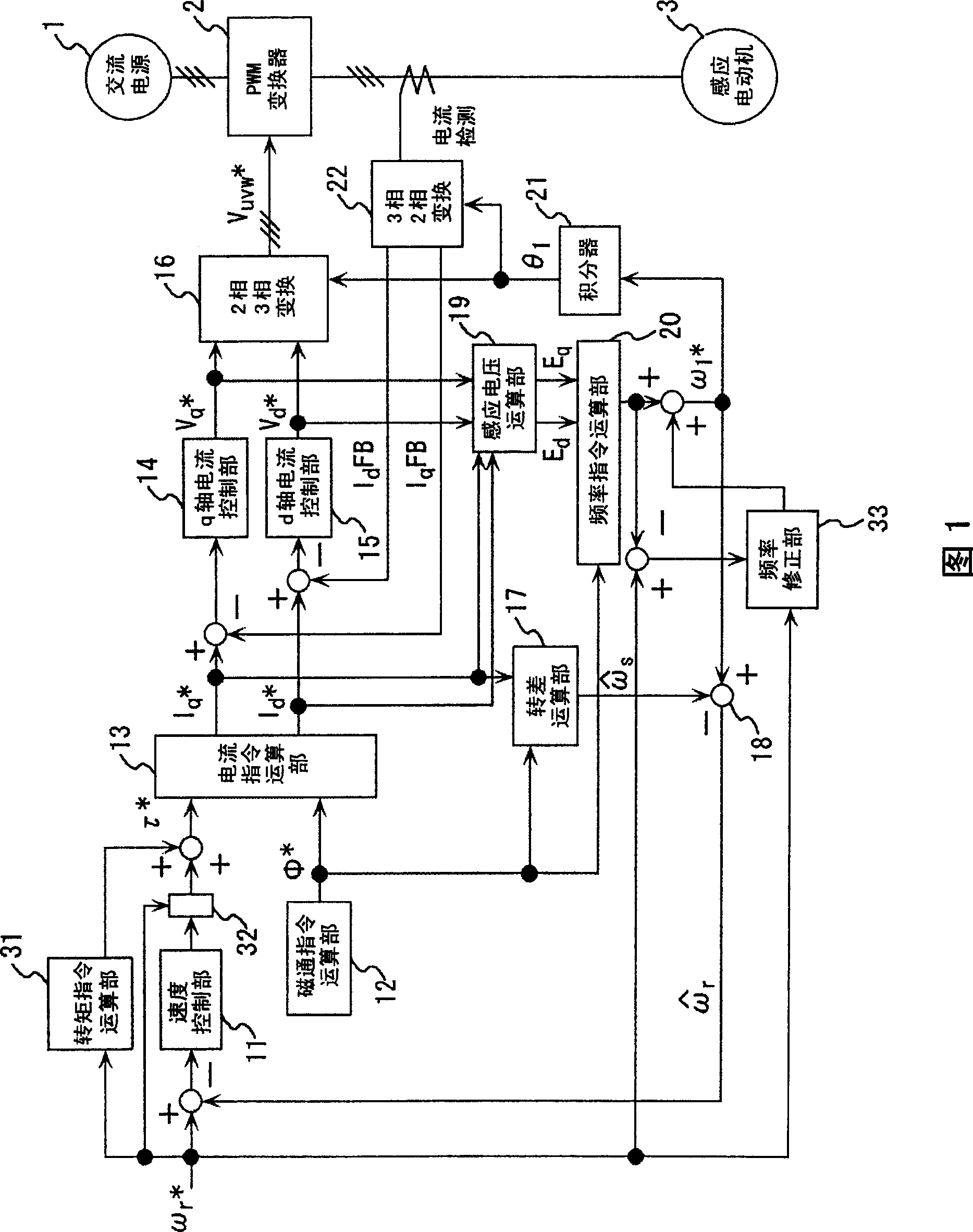
With reference to FIG. 1 , the motor drive device according to this embodiment will be described for the parts different from the conventional art shown in FIG. 8 . The first torque command is calculated by the speed control unit 11, and by the torque command calculation unit 31, according to the speed command value ωr * Calculate the second torque command. The synthesis of the first torque command and the second torque command is called torque command τ * . In the speed control output correction part 32, the output of the speed control part 11 is reduced to zero at the time of starting. Therefore, according to the speed command value ωr at startup * Computational torque command τ * , and the field current command value Id is calculated by the current command calculation unit 13 * , Torque current command Iq * . In addition, the term "starting" means the period during which the speed of the motor changes from 0 to rotation, and the term "after starting" means t...
Embodiment 2
[0023]
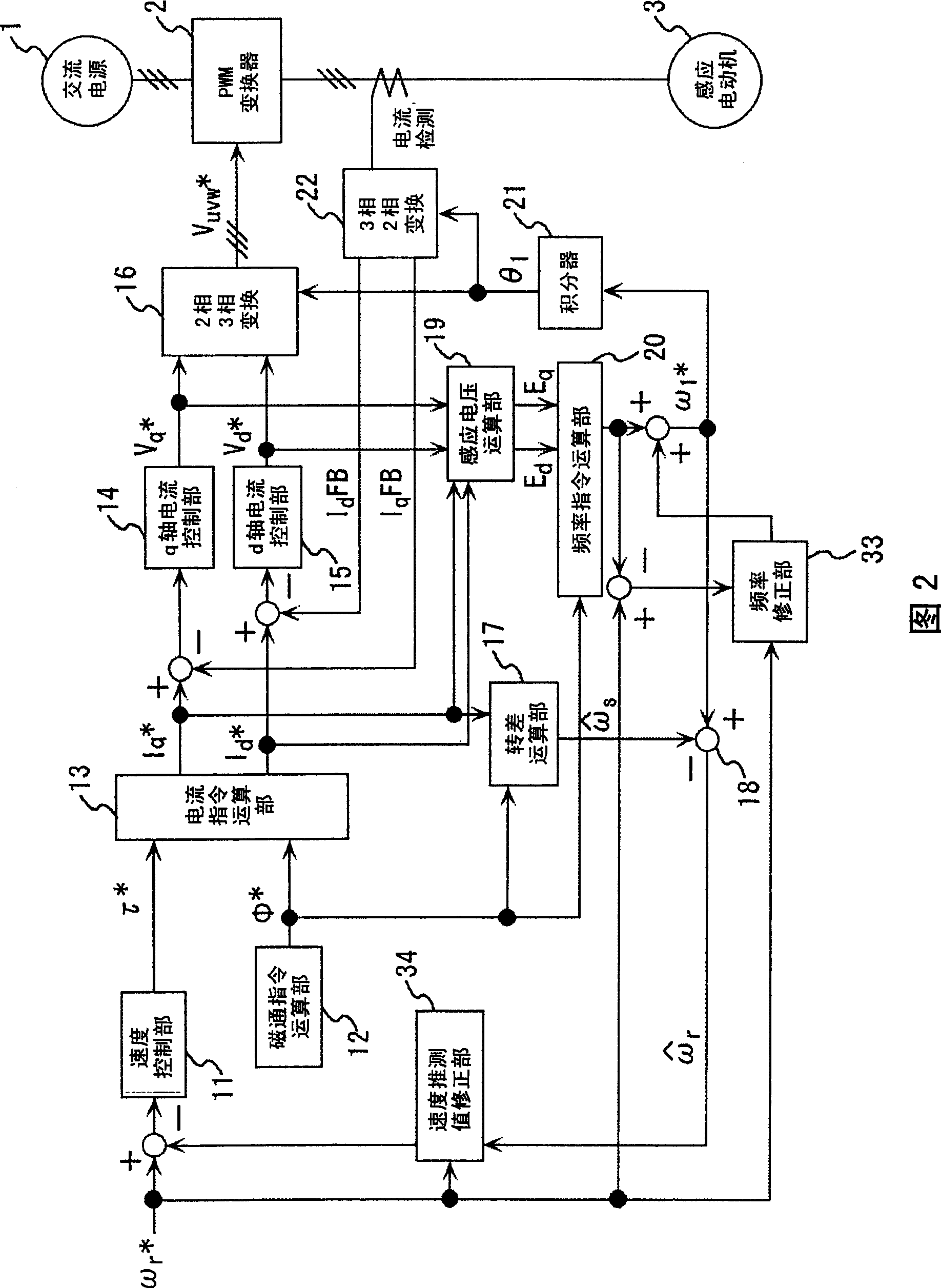
Regarding the present embodiment, differences from the first embodiment will be described using FIG. 2 . In the first embodiment, instead of the torque command calculation unit 31 in FIG. 1 , a speed estimation value correction unit 34 is designed to lower the speed estimation value at the time of starting. Thus, the speed control unit 11 only uses the speed command value ωr * The control is the same as in Embodiment 1, according to the speed command value ωr * , to calculate the excitation current command Id * , Torque current command Iq * , frequency command value ω1 * , so it is not affected by the speed estimation error, etc., and the desired torque can be generated at the time of starting.
Embodiment 3
[0024]
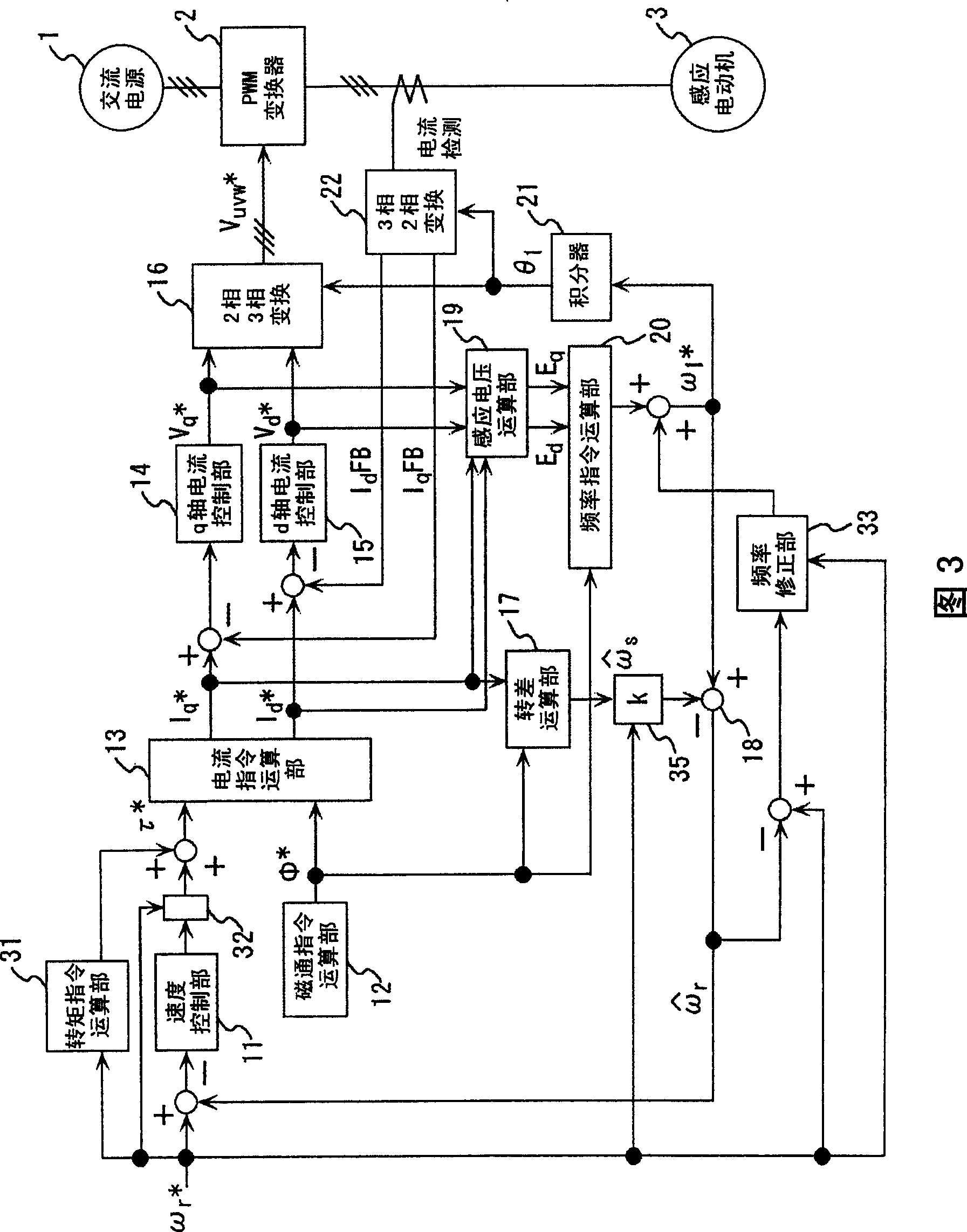
Regarding this embodiment, differences between Embodiment 1 and Embodiment 2 will be described using FIG. 3 . The result obtained by multiplying the output of the slip calculating unit 17 by k by the slip speed correcting unit 35 is used as the slip speed, and the sum frequency command value ω1 is obtained. * The difference, the calculation speed estimated value ωr^. k is 0 or more and less than 1 at the time of starting, but k returns to 1 when the predetermined speed is reached as described in Embodiment 1 after the motor is started. Thereafter, the output of the speed control output correction unit 32 is returned from 0 to the output value of the speed control unit 11 , and the outputs of the torque command calculation unit 31 and the frequency correction unit 33 are decreased to 0. Judgment during startup and after startup is the same as in Embodiment 1. In this embodiment, use (Equation 9) to find the frequency command value ω1 * .
[0025]
ω1 * =ωr * +ωs...
PUM
 Abstract
Description
Claims
Application Information
 - R&D
- Intellectual Property
- Life Sciences
- Materials
- Tech Scout
- Unparalleled Data Quality
- Higher Quality Content
- 60% Fewer Hallucinations
Browse by: Latest US Patents, China's latest patents, Technical Efficacy Thesaurus, Application Domain, Technology Topic, Popular Technical Reports.
© 2025 PatSnap. All rights reserved.Legal|Privacy policy|Modern Slavery Act Transparency Statement|Sitemap|About US| Contact US: help@patsnap.com


