Interior permanent magnet rotor and method for manufacturing the same

A manufacturing method and magnet technology, which are applied in the field of manufacturing magnet-embedded rotors and magnet-embedded rotors, and can solve problems such as permanent magnets being easily demagnetized

Inactive Publication Date: 2017-03-15
JTEKT CORP
View PDF2 Cites 2 Cited by
  • Summary
  • Abstract
  • Description
  • Claims
  • Application Information

AI Technical Summary

Problems solved by technology

Therefore, as described above, when the length of the orientation direction of the permanent magnets at the radial end portions is shortened, the permanent magnets tend to be easily demagnetized during the use of the rotor.

Method used


Image

  • Interior permanent magnet rotor and method for manufacturing the same
  • Interior permanent magnet rotor and method for manufacturing the same
  • Interior permanent magnet rotor and method for manufacturing the same

Examples


Embodiment Construction

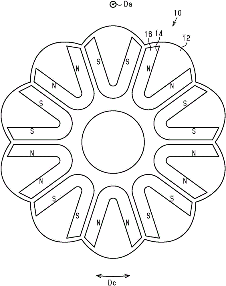
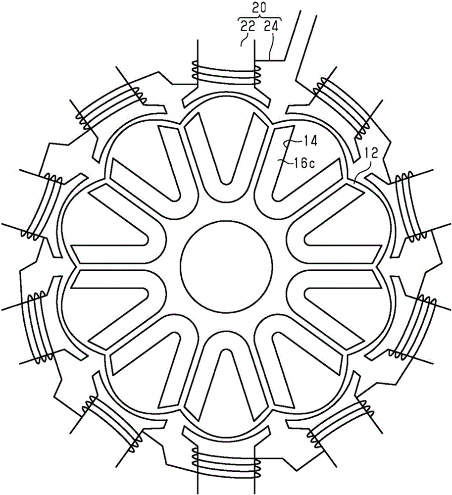
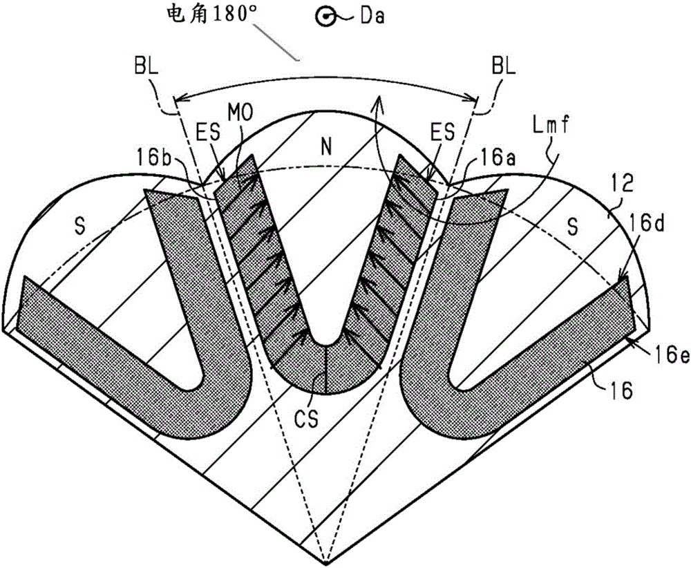
[0038] Next, a first embodiment of a magnet-embedded rotor will be described with reference to the drawings. figure 1 The illustrated rotor 10 is built into an embedded magnet synchronous motor (IPMSM). The IPMSM constitutes an electric power steering (EPS). The rotor 10 includes a magnetic core 12 and permanent magnets 16 formed of a soft magnetic material. The magnetic core 12 is formed by laminating a plurality of silicon steel sheets, that is, electromagnetic steel sheets, and has functions of holding a magnetic circuit, the permanent magnets 16 , and generating and transmitting rotational torque. The magnetic core 12 has ten insertion holes 14 penetrating in the axial direction Da. The cross-sectional shape of the insertion hole 14 perpendicular to the axial direction Da is substantially U-shaped. The insertion holes 14 are evenly arranged in the circumferential direction Dc of the magnetic core 12 . A permanent magnet 16 is embedded in the insertion hole 14 . The pe...


PUM


Abstract

The invention provides an interior permanent magnet rotor and a method for manufacturing the same. The interior permanent magnet rotor restrains demagnetization of permanent magnets embedded in a core 12. Each permanent magnet is formed by joining a first portion 16a and a second portion 16b at a connection CS. The first and second portions 16a, 16b extend from the outer side toward the inner side in the radial direction of the core 12. The outer end faces ES of the first and second portions 16a, 16b in the radial direction of the core 12 extend in an orientation direction MO as viewed in section perpendicular to the axial direction Da. The outside diameter of the core 12 gradually increases from the boundaries BL between a single magnetic pole and magnetic poles adjoining the single magnetic pole toward the middle of the single magnetic pole in the circumferential direction of the core 12.

Description

[0001] This application claims the priority of Japanese Patent Application No. 2015-175970 filed on September 7, 2015, and uses the entire content including the specification, drawings, and abstract here. technical field [0002] The present invention relates to a magnet-embedded rotor in which a permanent magnet is embedded in a magnetic core, and a method for manufacturing the magnet-embedded rotor. Background technique [0003] For example, US Patent Application Publication No. 2015 / 0137629 describes a rotor including permanent magnets extending from the radially outer side of the magnetic core to the radially inner side of the magnetic core. [0004] As a manufacturing process of the above-mentioned rotor, it is conceivable to adopt a process of forming an insertion hole in the core and applying a magnetic field from the radially outer side of the core to the material of the permanent magnet (magnet material) filled in the insertion hole. However, in this case, the magne...

Claims


Application Information

Patent Timeline
Patent Type & Authority Applications(China)
IPC IPC(8): H02K1/27H02K15/03
CPCH02K1/27H02K15/03H02K29/03H02K1/2766H02K2201/03H02K1/2713
Inventor 神田尚武柴田由之大野誉洋
Owner JTEKT CORP
Why Eureka
Try Eureka