

Method, system and device for realizing VLL in QinQ subinterface
A technology of sub-interface and export equipment, applied in the field of network communication
- Summary
- Abstract
- Description
- Claims
- Application Information
AI Technical Summary
Problems solved by technology
Method used
Image

Examples
Embodiment 1
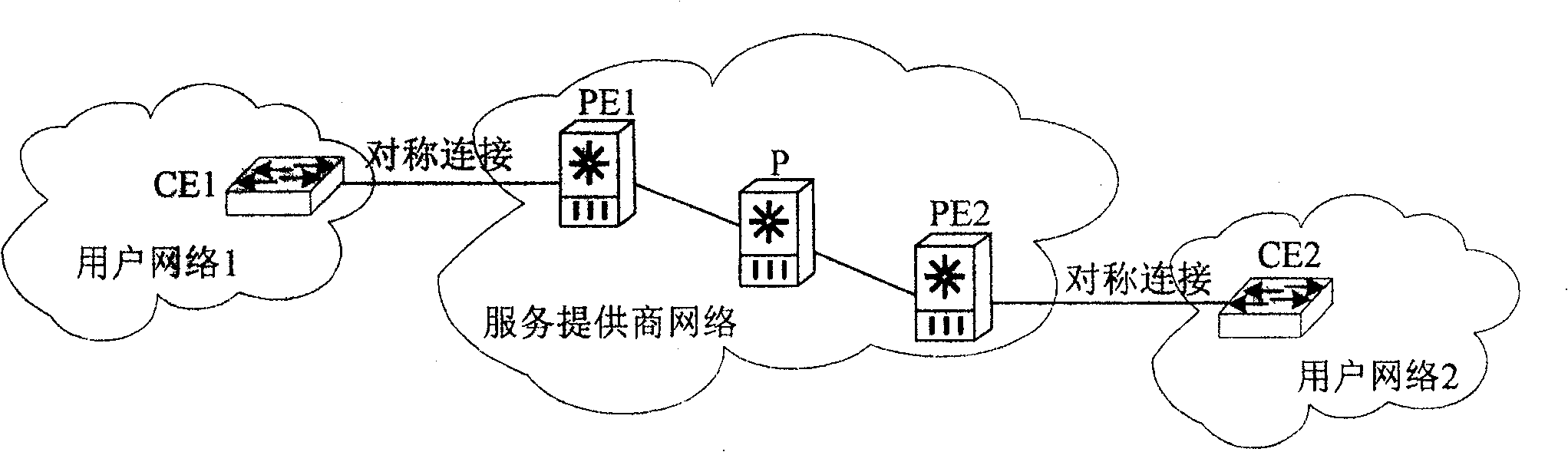
[0050] see Figure 5 , this embodiment provides a method for implementing VLL on a QinQ sub-interface, in order to Figure 4 The provided network device is taken as an example. The ingress device PE1 and the egress device PE2 in this embodiment need to be symmetrical devices, that is, they have the same QinQ sub-interface configuration, and the definite values are all definite values, and have the same definite value; The range segments are all range segments and have the same range, for example, they are all 100-200. The specific method is as follows:
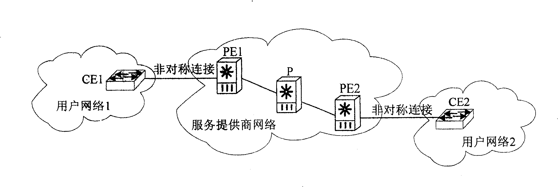
[0051] Step 501: Check whether the inner layer TAG of the QinQ sub-interface of the ingress device PE1 is a range segment, if yes, configure the corresponding QinQ sub-interface of the egress device to the same range segment, when receiving the report from the user end CE1 After the text, execute step 503, if it is not a range segment, but a definite value, then configure the corresponding QinQ sub-interface of the egress ...
Embodiment 2
[0066] see Figure 6 , this embodiment provides a system for implementing VLL on a QinQ sub-interface, including an ingress device and an egress device, wherein the inner TAGs of the QinQ sub-interfaces of the ingress device and the egress device are the same range segment,
[0067] Entry equipment includes:
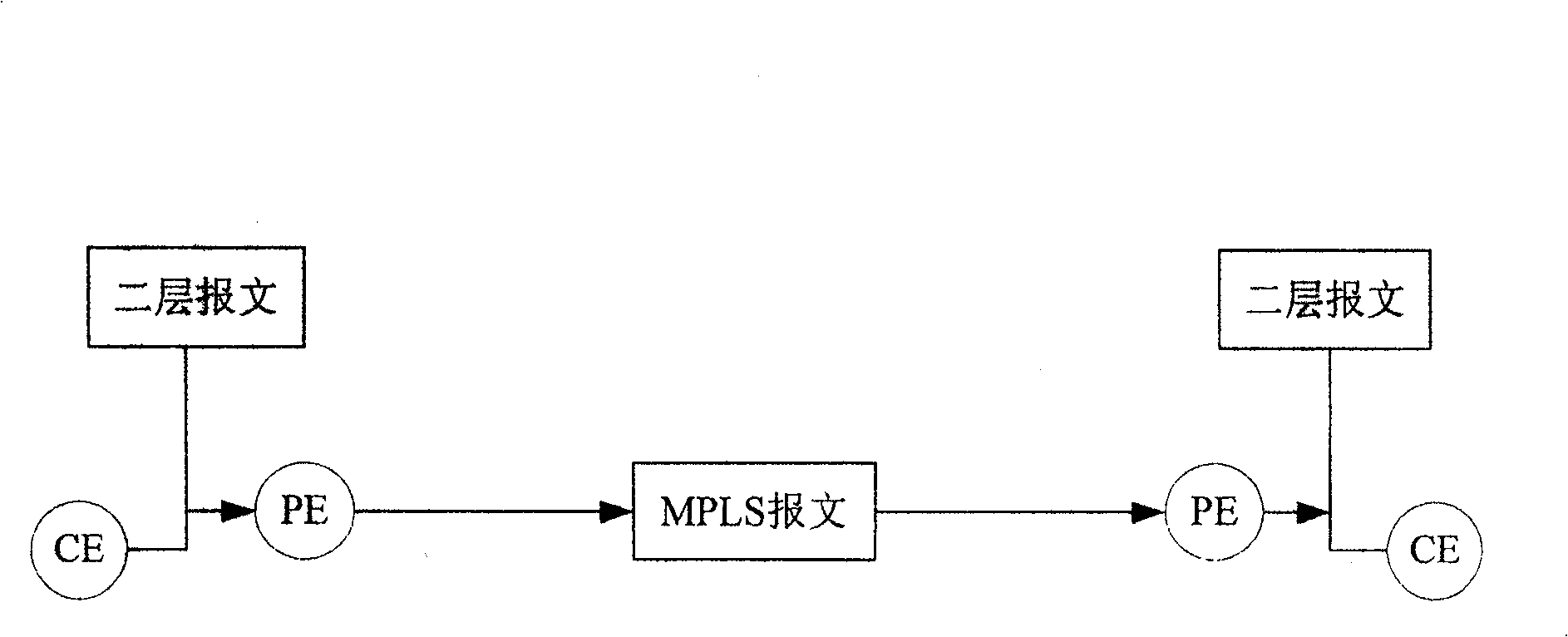
[0068] The outer layer TAG stripping module is used to peel off the outer layer TAG of the received message;
[0069] The message forwarding module is used to send the message after the outer TAG is stripped to the egress device through the MPLS tunnel after the outer TAG stripping module strips the outer TAG of the message;
[0070] Export equipment includes:
[0071] The message receiving module is used to receive the message sent by the message forwarding module after stripping the outer TAG;
[0072] The outer TAG encapsulation module is used for the message receiving module to encapsulate a new outer TAG after receiving the message with the outer TAG stripped off...
Embodiment 3
[0076] see Figure 7 , the present embodiment provides a device in a Layer 2 virtual private network, the QinQ sub-interface inner layer TAG of the device is a range segment;
[0077] When the device is used as an entry device, it includes:
[0078] The outer layer TAG stripping module is used to peel off the outer layer TAG of the received message;
[0079] The message forwarding module is used for the outer TAG stripping module to send the message after stripping the outer TAG to the peer device through the MPLS tunnel after stripping the outer TAG of the message.
[0080] The device is also available as an export device and also includes:
[0081] The message receiving module is used to receive the message after stripping the outer TAG;
[0082] The outer TAG encapsulation module is used for the message receiving module to encapsulate a new outer TAG after receiving the message with the outer TAG stripped off, and send the message encapsulated with the new outer TAG to t...
PUM
 Abstract
Description
Claims
Application Information